

 Spanish
  French
  German
  Simplified Chinese
 Powering MASSO Touch
CAUTION: Semiconductor parts inside the unit can be damaged by electrostatic discharge (ESD). When handling, care must be taken so that the devices are not damaged. Damage due to inappropriate handling is not covered by the warranty.
Open the enclosure by removing the four marked M5 HEX bolts. Please fully remove the four bolts and the swing open the top part towards the left side.
WARNING: When closing the enclosure and installing the M5 HEX bolts, please do not overtighten.

Installing the E-Stop button
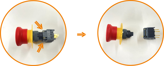
Press the two clips and pull the backside of the E-Stop button
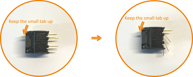
Bend the switch button as shown above.
NOTE: Keep the direction of the switch as marked by the tab.
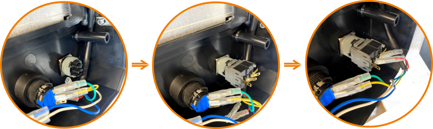
Install the E-Stop button, plugin the rear switch, and plug the wire crimps into the middle two pins.
Installing MPG connector
LCD Cable connector
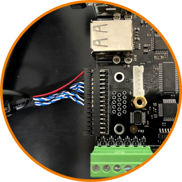
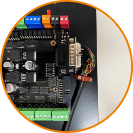
Powering the MASSO Touch
The MASSO Touch power supply connector is located at the top-right corner of the controller as seen in the picture below. MASSO Touch requires a power supply of 24 VDC with a minimum of 1.5 Amps output. Voltage not to exceed 25 VDC or be less than 23 VDC.
MASSO Touch will power on instantly once power is connected.
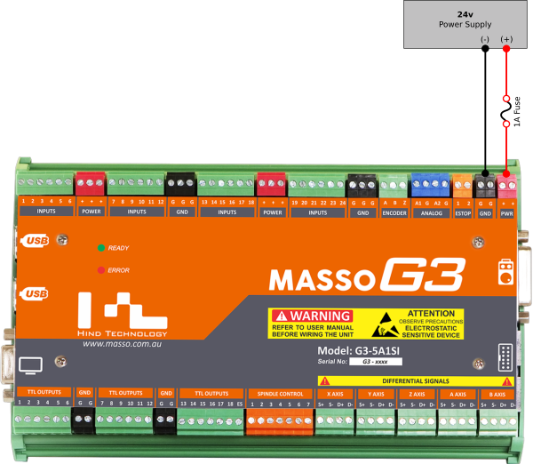
WARNING: The installation of a 1 amp fuse between your Power Supply and MASSO is required to protect against an accidental short circuit of the auxiliary power connectors on MASSO, such an event can damage the controller beyond repair.
WARNING: The MASSO Touch requires a power supply of nominal 24 VDC. Voltage not to exceed 25 VDC or be less than 23 VDC.
INFORMATION: There are multiple Power (Red-colored) and Ground (Black-colored) provided on the controller and can be used to easily wire drives, sensors and switches.
Some examples:
- The Power terminals can be used to provide voltage to sensors or switches for machine homing.
- The Ground terminals can be used to wire common ground signals between stepper or servo motor drives.
CAUTION: When using the auxiliary Power and Ground terminals on the controller the total current draw must not exceed 500mA across all terminals. Connecting high current loads can damage the controller beyond repair.