- Tool 0
- The laser pointer tool is used to provide a reference point to zero your X & Y axis.
- Selecting a point on your stock and zeroing your X & Y coordinates will automatically transfer them to the other spindles on your machine.
- The Dry Run laser pointer can be used to do a dry run of your machined part to ensure that it will fit on your stock.
- While performing a Dry run of your Gcode file it will ignore Coolant on / off Gcodes as well as tool changes and changes in Z axis height.
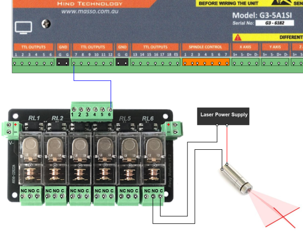
- A TTL output can be assigned to turn the laser pointer on and off and will automatically turn on when the Laser pointer is selected. This can be done using a MASSO relay module if needed.

Laser pointer Output
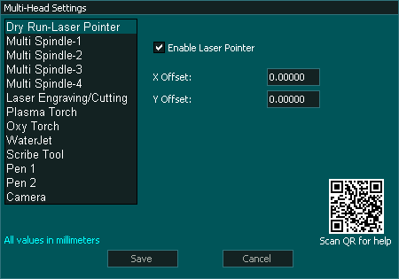
Multi-Head Settings
INFORMATION: To exit Dry run mode you must press the Dry Run Button  and the laser will turn off and you will return to the previous tool. You can not exit dry run by changing to a different tool as Dry Run ignore tool change requests.
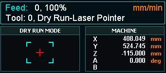
The Dry Run Laser pointer
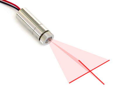
- The Laser for this is a small low power laser typically 5mW or less and may be a spot or cross hair as required. In general the lower power the laser is the easier it is on the eyes to view however this must be balanced with ambient light levels.
Connection and configuration
- Configure a TTL output as a Laser Pointer On/Off
- Wire as per the diagram below. Ensure that you provide the correct voltage to your Laser or you will damage it.
- Enter the X & Y Offset value from your main tool that you will be using as a reference for the machine. This is usually the Main Spindle, Plasma head or WaterJet head.
- All Multi-head offsets must reference from the same Head.
Laser Alignment
- The Dry run laser can be mounted to either the Z or X axis.
- If the Laser is mounted on the Z axis the Laser must be aligned so that it's position does not change when the Z axis is raised and lowered.
- To align the Laser, mark a spot on the table and them raise and lower the Z axis and if the laser point moves with respect to the reference point move the laser in it's mount to bring back into alignment. This alignment needs to be done in both the X & Y axis and at completion of the alignment process the laser point will remain pointing at the reference mark over the entire Z axis range of movement
- If the laser is mounted on the X axis it must also be aligned in the X & Y axis to ensure that as the material height changes the laser points at the same spot.

Calibrate a Dry Run Laser to the Main Head
- All Multi-head offsets must reference from the same Head. This is the Main Head Eg spindle on a Mill
- Ensure the head that you are calibrating to the main head has it's offsets in the Multi-head settings page set to 0
- Home your machine.
- Ensure the current tool is your main head and if not change to it using MDI eg T1 M06
- Make a small reference mark using the main head tool. In case of a spindle a V-bit can be used to make a well defined reference mark.
- Zero the X & Y axis DRO
- Change to Dry run Laser by going to MDI and pressing the
 button
 - Jog the Laser pointer to the reference mark made by the main head and align.
- Read the X & Y axis DRO values and enter these values into the X & Y offset for the Dry Run Laser.
- The DRO readings will now show 0 on both the X & Y axis DRO if the correct values have been entered.
- If the values you enter doubles the DRO reading instead if making it 0, change it to a positive or negative value. eg 106.753 would become -106.753 and visa versa
- Exit Dry Run laser by pressing the MDI button
- Your Dry Run Laser is now calibrated.
Example wiring diagram
WARNING: The example below is intended to illustrate the concept of how such a system could be wired. The actual wiring of your machine will depend on the hardware used and it's requirements. Please consult your user manual for the correct way to wire your selected hardware. If unsure please consult a qualified electrical engineer to assist with wiring of your machine.
Using the Dry Run Laser Pointer
- In MDI select Dry Run This will Automatically turn the Laser on and put MASSO into Dry Run mode.
- While in Dry Run Mode the Dry Run Mode icon will flash on screen.

- While in Dry Run Mode the Spindle or Plasma torch will not start, The coolant will not turn on and the Z axis will not move under Gcode control. This includes probing cycles.
- You can use the laser to Zero your X & Y axis if desired. When you leave Dry Run mode the coordinates will be offset with respect to the new selected tool.
- You can load your Gcode file in Dry Run if you have not already done so.
- Run you Gcode File as required. The laser will show the how the tool path will go when you machine the part.
- To Exit dry Run Mode Press the Dry Run Button and the laser will turn off and you will return to the previous tool.
- You cannot exit Dry Run mode by changing to a different tool as it ignores tool change requests.
- There are no dedicated buttons on the F2 Screen associated with this tool.
Dry Run without a Laser
Dry Run can be used without a laser pointer.
If you are not using a laser leave the X & Y axis offsets set to 0 in the Multi-Head Dry Run Laser pointer setup screen.
This will move your spindle, Plasma torch or other head around the table indication the cutting path.
The Z axis will not move while under Gcode control.


 Spanish
  French
  German
  Simplified Chinese