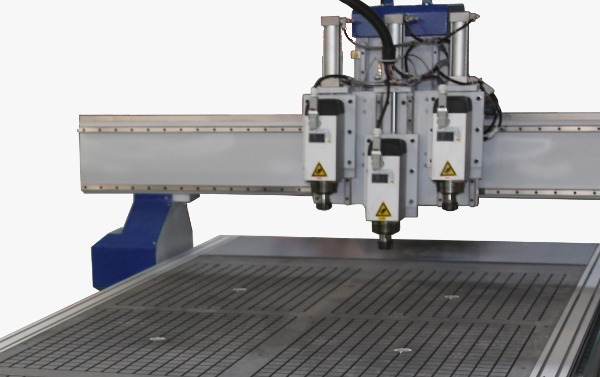
- Multi Spindle is an addon feature that can be purchased for your MASSO G3 or MASSO Touch.
- Tools 101 - 104
- Each head is mounted to a common Z axis and is moved into position using the Up/Down signal for that head unit.
- The move into position is usually done using a pneumatic cylinder.
- Multi-head Spindle is not designed for machines that have individual Z axis drives
- Multi Spindles 1 to 4 provide an additional 4 spindles to be added to the Z axis. This gives a total of 5 spindles that can be configured in MASSO
- Each spindle will be configured in the Mutli-Head Settings page and can be individually enabled or disabled as needed.
- Each Multi Spindle has defined X & Y offsets from the Main Spindle center point or some other suitable reference point of the users choosing.
- Each Multi Spindle has a dedicated tool number and a corresponding tool entry in the F4 Tools & Work Offsets table.
- Differences in Z axis Tool length is managed within MASSO F4 tool table however please be aware that your Gcode must include a move to a safe Z height before changing between spindles to ensure that the new tool does not contact the material when the spindle changes. See the special note for Multi-head users in the M06 Gcode command.
- Then tools 101 to 104 are selected using the M6 command instead of the main spindle selecting the tool, the dedicated spindle will be selected instead.
- Multi Spindle 1 - Tool 101
- Multi Spindle 2 - Tool 102
- Multi Spindle 3 - Tool 103
- Multi Spindle 4 - Tool 104
- A dedicated Spindle select is available for each spindle including the main and can be assigned to any MASSO TTL output. These are used to move the spindle into position or retract it when not needed. It also switches the Spindle control to the selected spindle.
- A spindle VFD Run status input is provided to monitor when the spindle is running and prevent it switching to a new spindle until it comes to a stop.
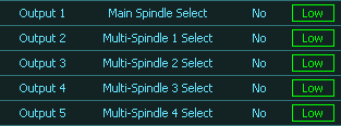
Multi Spindle Select Outputs

Spindle VFD Run status Input
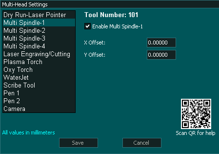
Multi-Head Settings

F4 Tools & Work Offsets
Configuration
- Select Enable on each Multi Spindle that you want to use. Enable only the spindles you will be using.
- The main spindle is always used in a multi spindle setup and you can enable up to 5 spindles in total.
- Assign a TTL output for the Main Spindle select.

- Assign a TTL output for Multi- Spindle select for each Spindle that you enable.

- Assign an input as Spindle VFD Run Status.

- Configure your VFD to output a signal when the VFD is running. All VFD's should have this option and can provide the output as either an Open Collector or as a relay output. Set the Spindle VFD Run status input to show logic Low when the VFD is idle and Logic High when the VFD is running. The VFD Run status input is provided to monitor when the spindle is running and prevent it switching to a new spindle until it comes to a stop.
- Under the Multi-head setting for each spindle you enable enter the X & Y offset value as referenced from the Main Spindle center point or some other suitable reference point of the users choosing.
INFORMATION: When MASSO starts and homes MASSO will home the X,Y & Z axis with all Head units retracted. The Main spindle will then into position and touch off on the Auto Tool Zero if you have it enabled as part of the homing routine. With this complete the Main spindle will retract and the tool that was last loaded into position will be lowered into position.
Multi-Spindle Logic
- Gcode command issued eg. T101 M6
- When a Tool change command is issued MASSO will checks which spindle is required.
- Tools 1-100 will select the Main Spindle and if the spindle is an ATC spindle it will work with the tool changer in the normal manner.
- If the Tool selected is 101 to 104 then Multi-Spindle 1 to 4 is selected.
- Multi Spindle 1 - Tool 101
- Multi Spindle 2 - Tool 102
- Multi Spindle 3 - Tool 103
- Multi Spindle 4 - Tool 104
- MASSO checks to see the status of the Spindle VFD Status Input and will wait for it to go low before proceeding.
- Which ever spindle is selected the corresponding Spindle Select output will go High.
- If tool 101-104 is selected the spindle will not do an Auto Tool Zero touch off as these tools should be measured when initially installed using the F4 table.
- If tool 1-100 is selected the main spindle may do an Auto Tool Zero touch off if it is enabled in the F1 settings.
Wiring Multiple Spindles
Spindle Select output
The Spindle Select output can be assigned to a spare TTL output.
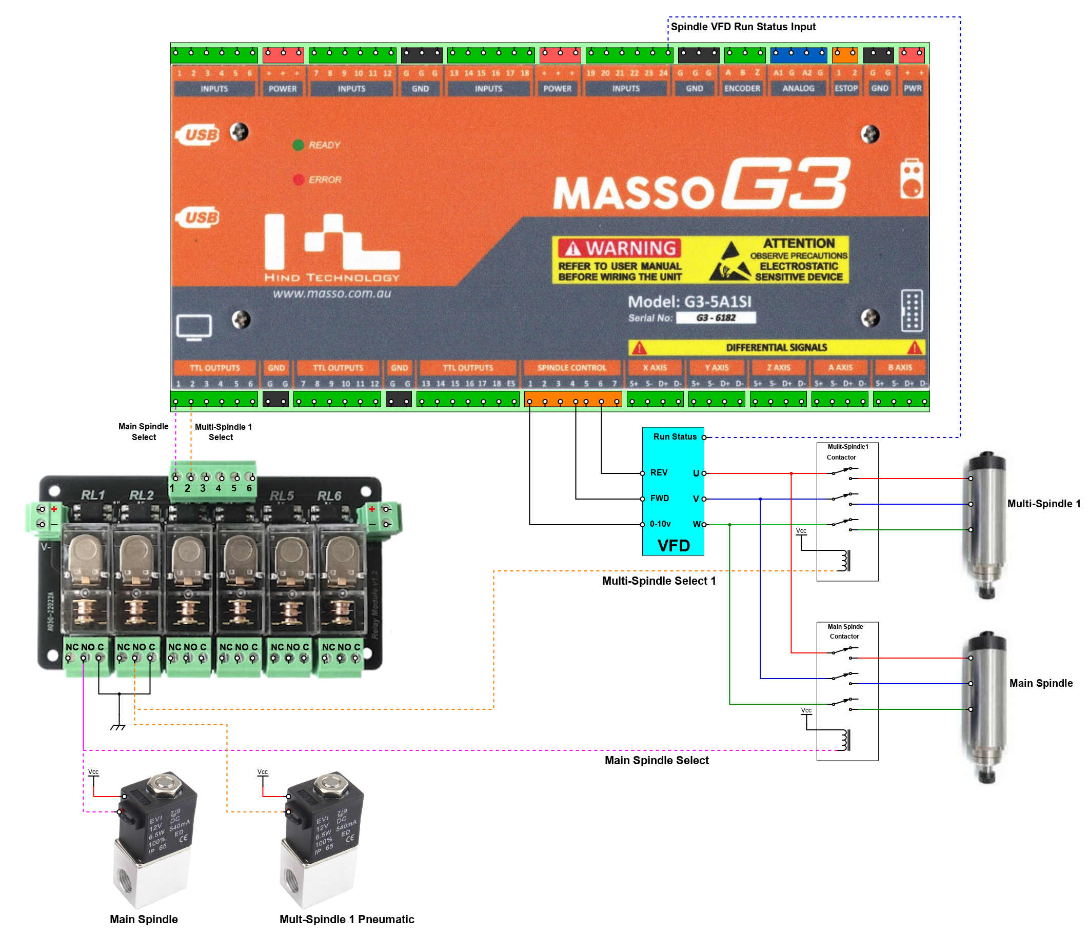
This output is responsible for moving the selected spindle into position and retracting the spindle when it is no longer selected. This is normally done using Pneumatic cylinders. When the output is high the pneumatic cylinder pushed the spindle down into position and when the output goes low the cylinder retracts.
The output also directs the Spindle control to the required spindle. This can be done using 2 methods.
- The Spindle control signals Speed, Forward & Reverse could be switched to the designated Spindle and each spindle would have it's own dedicated VFD.
- The Machine has one VFD and the 3 Phase power is switched to the selected Spindle using a 3 Phase contactor relay unit.
WARNING: When using a single VFD the Spindle VFD Status Input must be assigned and the VFD set to output the VFD status signal as switching loads on a running VFD may cause damage to the VFD and other equipment.
WARNING: Extreme care is required when wiring a VFD. The example wiring below is intended to illustrate the concept of how such a system could be wired. The actual wiring of your machine will depend on the hardware used and it's requirements. Please consult your user manual for the correct way to wire your VFD and other hardware. If unsure please consult a qualified electrical engineer to assist with wiring of your machine.
Example wiring diagram
Setting Tool Z offset
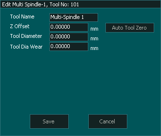
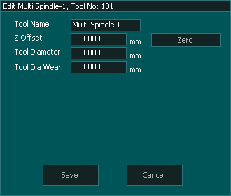
To set the Z offset for the tool in your Multi-Spindle go to the F4 tool table and double click on the required tool 101 - 104
Multi Spindle 1 - Tool 101
Multi Spindle 2 - Tool 102
Multi Spindle 3 - Tool 103
Multi Spindle 4 - Tool 104
Press Auto Tool Zero and the tool in the spindle will be measured.
The tool does not need to be measured again unless you change the tool in the spindle.
If you do not have Auto tool zero set up or enabled on your machine you will not see the Auto Tool Zero option but a Zero Option instead. You will then need to manually zero the tool.
It is highly recommended that you set up and use Auto Tool zero for measuring tool lengths.
Measure tool Length
Please Note that as each of the Multi-Spindle tools are of fixed length and were measured when the tool was installed MASSO excludes these from using Auto Tool Zero on a tool change.
The Mains spindle will continue to use Auto Tool Zero in the normal manner if enabled.


 Spanish
  French
  German
  Simplified Chinese
