Spanish
  French
  German
  Simplified Chinese
 Pen 1 & 2
The Pen tool can be used with marker pens and other similar tools as needed
- Tools 116 & 117
- To change to Pen issue a T116 M06 or a T117 M06 command in MDI and include this in your Gcode file to ensure that it changes to the correct screen when you run your Gcode file
- The X, Y & Z offset relative to another head can be entered in the Multi-Head Setting page
- A Pen Up/Down output is provided for each pen and can be assigned to one of the TTL outputs.
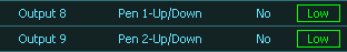
Assign Pen outputs
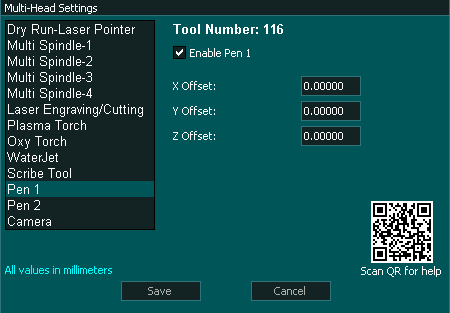
Multi-Head Setting
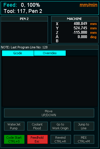
F2 Screen
Configuration
- Enable Pen 1 and Pen 2 as required in the Multi-head screen.
- Assign an output for Pen up /Down.
- Enter the X, Y and Z axis offset from the reference tool into the Pen 1 & Pen 2 Multi-Head setting screens. This could be the Main spindle or a Plasma torch.
Pen Logic
- The appropriate Pen up/Down output will go High. This output is used to push the Pen down into position.
- If a different tool is selected the Pen Up/Down output will go Low which will pull the Pen up into the idle position.
- There is a button on the F2 Screen when Pen 1 or 2 is selected which allow the user to move the Pen up and down as needed.
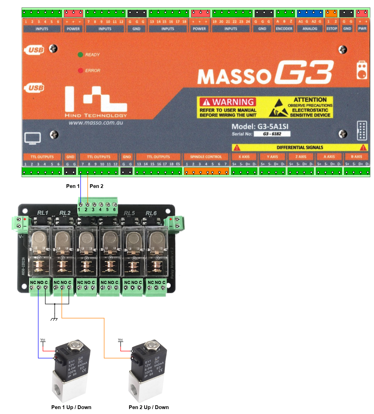
Wiring a Pen
Example wiring diagram