Spanish
  French
  German
  Simplified Chinese
 Wiring & Setup
WARNING: Power off the machine and electronics when wiring, unplugging or connecting any connectors or connections.
WARNING: Double check your connections on the DB9 male and DB9 female connectors as these can be easily mistaken and if connected at the wrong connector can damage the entire controller.
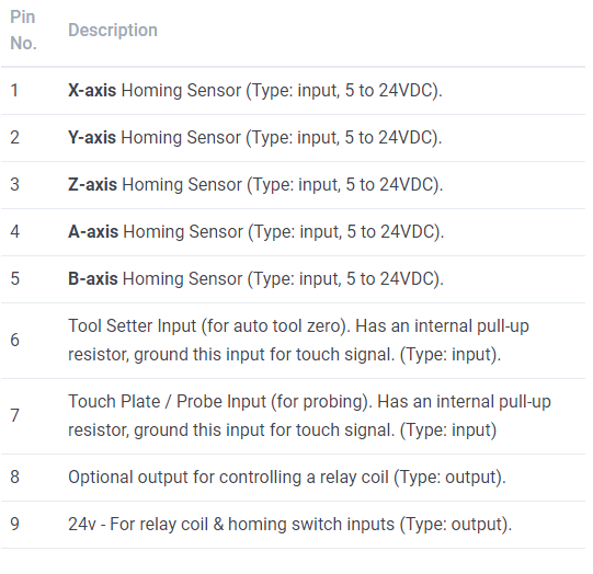
DB9 (MALE) Connector on the control box
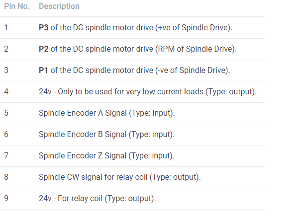
DB9 (FEMALE) Connector on the control box