Spanish
  French
  German
  Simplified Chinese
 Homing Sensor Identify & Connecting
Homing Switch Overview
This document provides wiring and input configuration information based on the type of switch and wiring you are using. Due to the large variety of switches on the market we are unable to provide individual support for your chose sensor. This document will help you identify and connect your chosen sensor or switch and provide information on how to connect. Please use this in concert with the information that came with sensor. This document seeks to help identify Electronic switches such as proximity, optical or hall effect with the use of a voltmeter and some basic testing.
Wiring also provided for mechanical switches such as lever, push button and magnetic reed switches at the bottom of the page. Use a continuity tester to identify if your switches are normally open or closed and wire accordingly. Always used normally closed if you have the option of additional safety.
HINT: All MASSO inputs are optically isolated and require a voltage of 5V to 24V from your sensor to register an input.
INFORMATION: To invert an inputs logic, highlight the input and press the spacebar on your keyboard. All Homing inputs must show LOW when not operated and change to HIGH when active.
INFORMATION: If you are unsure what homing switch to purchase and how to wire it then MASSO supplies a Homing switch with full wiring instructions available.
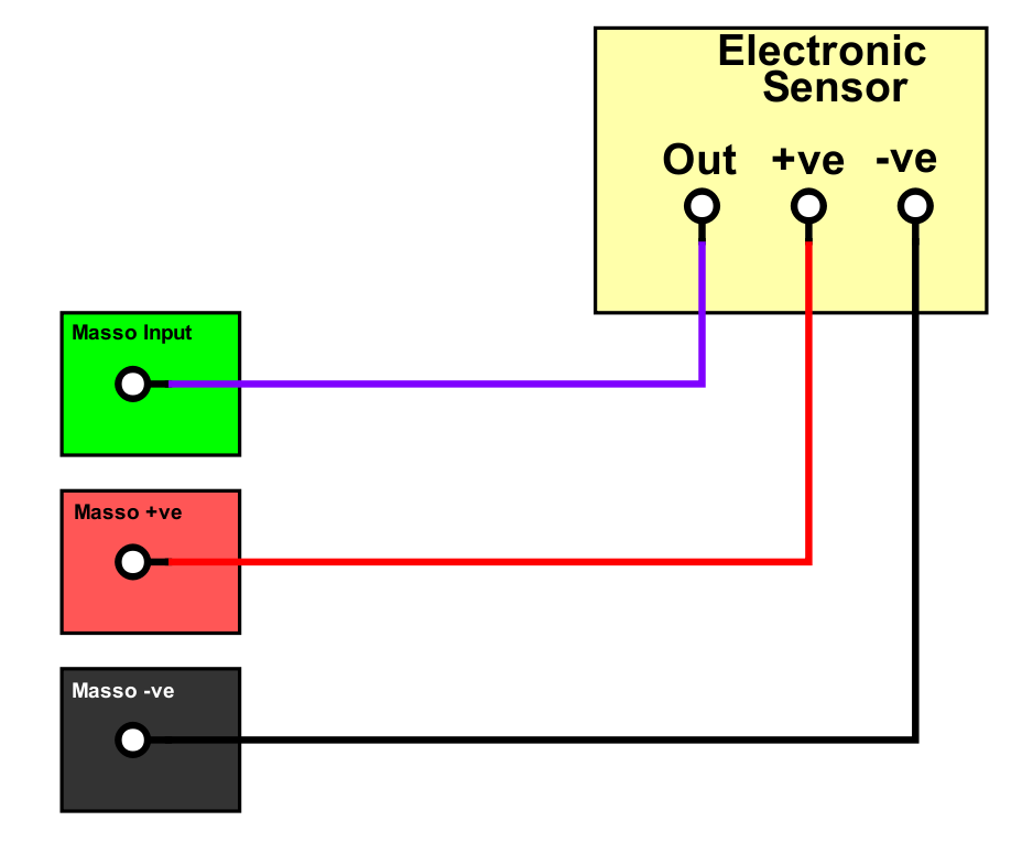
Powering your Homing sensors
How to wire the MASSO homing sensor
Identify your Electronic homing switch type
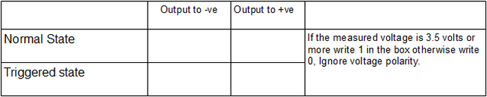
Complete the following testing matrix using the steps below to identify your sensor type and required wiring / input setting.
Step 1: Connect your sensor to a suitable power supply
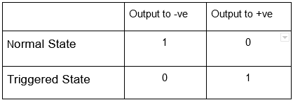
Step 2: With sensor in normal state measure the voltage between the output & +ve and the output &-ve record the results in the table below. If the voltage is greater than 3.5 volts record a 1 otherwise record a 0. Ignore the polarity shown on the meter.
Step 3: Trigger the sensor and measure the voltage between the output & +ve and the output &-ve record the results in the table below. If the voltage is greater than 3.5 volts record a 1 otherwise record a 0. Ignore the polarity shown on the meter.
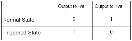
Electronic Homing Switch Matrix

Step 4: Find the matching table below and use the wiring diagram and input configuration indicated.
Sensor Types and Wiring
Type 1

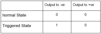
Type 2
Note: Invert MASSO input for Type 2 sensor

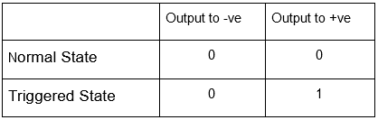
Type 3
Type 4

Note: Invert MASSO input for Type 4 sensor
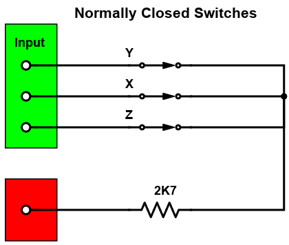
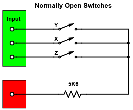
Mechanical Homing Switch connection
There are 2 ways of connecting Mechanical switches but the preferred method is using a normally closed switch which is the more fail safe method of the two. Should a homing switch wire break, the homing input will go high making MASSO think the Homing switch is already active so will attempt to back off the switch and will stop after 10mm.
In case of normally open switches a broken wire will not change the input and MASSO will drive the entire distance allowed before giving a homing alarm.
Note: Invert MASSO inputs when using Normally closed switches