Connect an Opt Lasers PLH3D
This page shows how the PLH3D 6 watt laser with CNC adapter was connect to MASSO for our Laser testing.
It comes with premade cables and only 2 wires needed to be connected to get the laser up and running.
The addition of 2 more wires to the Estop relay adds another level of safety to the setup and is highly recommended.
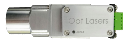
The kit came with the Laser, a CNC Adapter and all cables necessary to connect it to the MASSO CNC Controller as well as a pair of safety glasses suitable for use with the Laser.
It also included a magnetic nozzle and Magnetic docking station so that you can remove it when not in use.
The PLH3D CNC Adapter provided with the kit is an interface between the Laser and MASSO which has various safety interlocks. These can be used to help ensure that the laser can be locked when not in use to prevent unauthorized use and provides other safety features such as a place to connect the Emergency stop.
Configuring MASSO
- Configure MASSO output 11 for the LASER Engraving/Cutting output as shown.

- No other output can be used for this function as it includes special hardware to output a PWM signal.
- An output can be assigned to move the Laser into position when Laser is selected.

- An output can be assigned for Air assist is required.

- Go to the Multi-Head setting page and select Laser Engraving/Cutting.
- Click Enable.
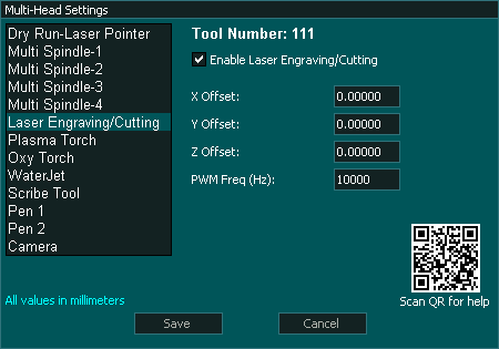
- Set the PWM Frequency for your Laser. It is recommended that you select a value of 10Khz though this will depend on the power of your Laser and the maximum feed rate you will be moving at. Since power is controlled by turning the Laser on and off very rapidly, if you have a low PWM frequency and move quickly you could get a line that has areas where the laser was on or off - - - - - - - - A frequency of 10Khz should be a good balance.
- PWM can be set between 4Khz & 60Khz
- X,Y & Z offset is the distance from the Main spindle or other Main tool if using Waterjet or Plasma. This can be measured zeroing the DRO's, making a spot with the Laser and then jog the Main spindle over to the center of the spot and reading off the X Y Y coordinates on the DRO's. These will be your offsets. The Z offset will be determined by the focus point of your Laser offset to the Z zero point of your Spindle tool. It would not be uncommon to leave the Z offset set to 0 and to manually zero the Laser when doing the job. Offsets are only needed when switching between the Laser and other tools and only if they are part of the same Gcode file.
- Configuration complete.
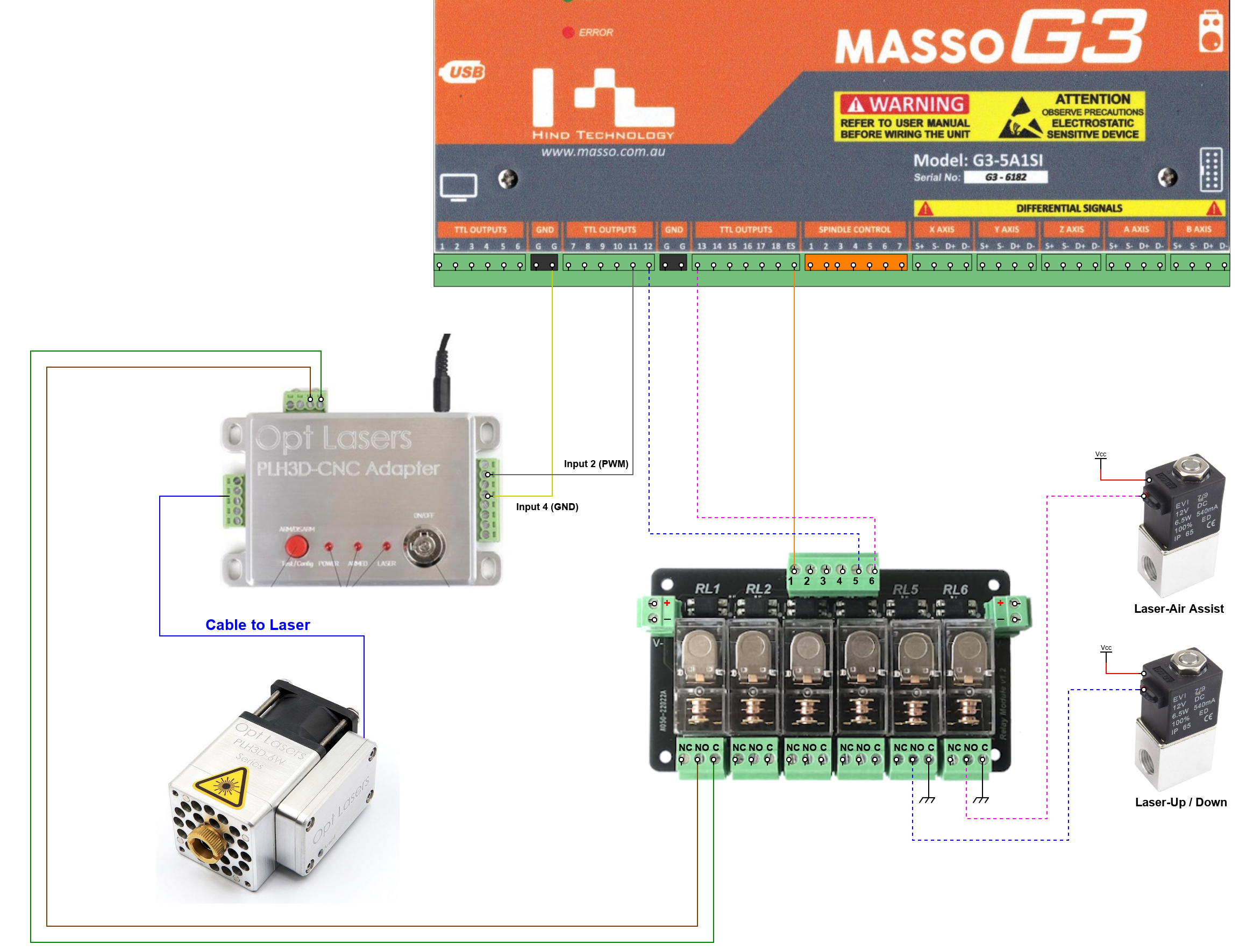
Connecting to MASSO
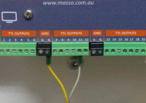
You can use either set of the GND terminals for the yellow wire. Use which ever us convenient to you
Installing the PLH3D-CNC Adapter
Connect as shown in the wiring diagram above.
You can see the wire colours used to connect the TTL and Estop relay.
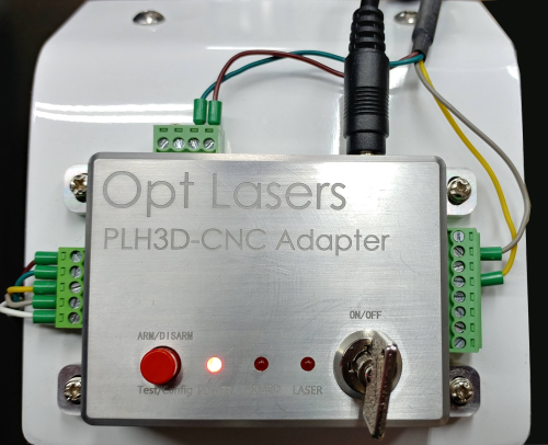
Estop Connection
To connect the Estop to the Laser a MASSO Relay was used and connected to the ES output on MASSO. The normally open contacts of the relay was connected to one of the External switch inputs on the CNC adapter. To do this remove one of the pre installed links on Switch connector along the top of the CNC Adapter and connect the Normally open and Common relay contacts of your Estop MASSO relay in place of the link as shown above. This will remove power from the Laser whenever the Estop is operated or MASSO is powered off.
Laser Up/Down
- An output is provided to allow the Laser to be automatically lowered into position and raised back up once another tool is selected.

- As soon as the Laser tool is selected the Laser Up/Down output will go High. eg.T111 M6
- When another tool is selected the Laser Up/Down will go low. eg.T1 M6
- The Laser can be lowered by either a Pneumatic cylinder or a linear actuator.
- The Output can also be used to power the Laser on and off for additional safety.
Air Assist
- An output is provided for Air assist if your laser supports it. Air assist is used to increase the cutting power of your laser as well as improve the cut quality.

- An M8 Gcode command will turn the air on and an M9 will turn it off.
- An air solenoid can be connected to turn the air on and off as required.
Programming the CNC Adapter
The CNC adapter can be configured in many ways and needs to be set correctly to work with MASSO.
You will see the configured mode whenever you turn the Laser on in the first second before the Power LED turns on.
The CNC Adapter is correct if you see the Laser LED come on by itself before the Power LED turns on.
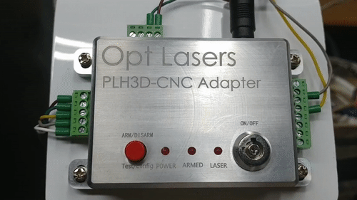
This what you see when you turn the Laser on
Instructions on setting the CNC Adapter can be found on the Opt Lasers Site. CNC Adapter Manual
Docking Station
The Laser kit has a docking station. Ideal if you do not want you Laser permanently attached to you machine.
The Docking station uses powerful rare earth magnets to achieve a good connection of the Laser to the machine and it also passes all electrical signals to the Laser head.
When not in use there is a cover to protect the docking station.
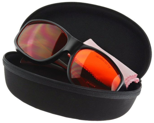
Safety Glasses
The most important part of any Laser is a Quality pair of safety Glasses.
The Laser Safety glasses supplied with the kit are high quality and help reduce the probability of light entering the user’s eye from a diffusely backscattered laser light.
They are rated as OD 7+ over the range of 190 to 540 nm, blocking deep ultraviolet to green including violet and blue light.
You only get one pair of eyes and they don't grow back.


 Spanish
  French
  German
  Simplified Chinese