

 Spanish
  French
  German
  Simplified Chinese
 Setup Rotary Axis
There are 2 types of rotary axis used on a CNC machine. The Maximum and minimum travel settings will change depending on which type or rotary axis you are setting up.
- The first and most common is a 4th axis traditionally use on a Mill. This is usually the A axis and it rotates the stock in one axis only while the Z axis moves along it's length in the manner of a lathe.
- The second is as part of a 5 axis machine where the A & B axis are used to move the stock in 3D space for machining.
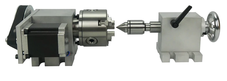
Rotary 4th Axis
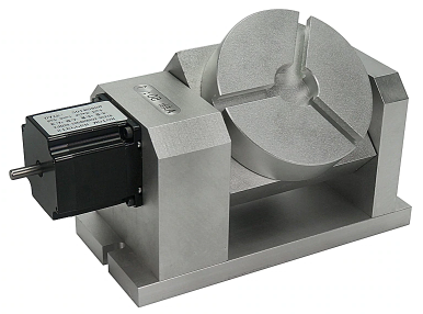
5 Axis
Rotary axis settings are angular and not linear. There is no advantage to using huge step rates with large gear ratios. Breaking one rotation into a million steps will not help accuracy and give you a rotary axis that is slow. A value of 8000 to 10000 Pulses per revolution should be more than enough for most applications. Only when you are turning huge diameters 1 or 2 metres in diameter will you benefit from large Drive: Pulse per Revolution rates.
INFORMATION: Make your Motor: Degrees per revolution = 360 and this way you will always get a whole number for the Drive: Pulses per revolution. It is also easier to calculate and will make more sense when you are reading it.
How to Calculate Rotary axis settings
Gather the following information:
The number of steps per revolution of your motor. For example most steppers are 1.8 deg motors with 200 steps.
The gearing reduction ratio between the stepper and the rotary axis output. If you do not have any gearing the ration is 1.
Microstepping set on your motor drive.
- Calculate pulses per revolution as follows:
- Motor: Degrees per revolution = 360 (Please note this value is fixed and cannot be changed)
- Drive: Pulses per Revolution = Motor steps per revolution x Gearing x Microstepping
- Maximum Feed rate = Set a value that suits your rotary axis capabilities. Remember that this is in degrees per minute and not RPM
- Acceleration = This value will depend on your machine’s drives and cannot be calculated. These are found by actual testing on your machine.
- Maximum and Minimum Travel = If this is a Mill Rotary 4th axis by setting large maximum and minimum travel will allow you to use it like a wood lathe and sand your masterpiece if your machined part is suitably shaped and your maximum feed rate is fast enough..
- Maximum and Minimum Travel = If this rotary axis is used as part of a 5 axis machine you may need to limit the travel of the axis to prevent it running into hard stops. Set the travel values accordingly.
- Backlash = Measure and set according to your machine's measured backlash.
WARNING: Always calculate the rotary axis setting. Do not run axis calibration. Unlike a linear axis which can vary due to component tolerances, a rotary axis will always calculate accurately.
INFORMATION: MASSO has a rotary axis unwind built into the G28 command. G28-return-to-machine-home
My Rotary Axis moves Slow
This is caused by confusing linear and rotary speeds. Your axis will move at the rate of the slowest axis and reasonable linear speeds can be very slow when changed to degrees per minute
and in the worse case scenario can make the machine look like they are not moving at all. A feed rate of 10 inch per minute will take 36 minutes for the rotary axis to complete 1 rotation. Check out Rapid Rotary to get a better understanding.
Additional resources
https://www.ganotechnologies.com/cnc/rapidrotary/
Homing sensor
A homing sensor may be set up on your rotary axis to home the axis.
- These can be mechanical, optical, magnetic or proximity sensors.
- The homing sensor must normally show Low on the F1 screen and change to High when triggered. Use the spacebar to toggle the input logic if yours is reversed.
INFORMATION: If you do not wish to install a homing sensor then set the rotary axis to Home in the Homing settings and MASSO will zero out the machine coordinates for the Rotary axis when you home the machine. This is a common setup for a rotary 4th axis.
Hard Limits
On a rotary axis the hard limit does not work as a rotary axis will pass the switch once every revolution. If you need to limit the axis travel please use your maximum and minimum travel limits.