

 Spanish
  French
  German
  Simplified Chinese
 Setup MASSO Mill
Quick Start Guide MASSO-G3 Mill Configuration
These notes have been created to assist new users to set up key configuration properties in MASSO.
This is not a full configuration guide but seeks to provide configuration guidance. Some items need to be configured in the correct order or things will not work as expected. It will also point out common pitfalls and hints for first time users. I understand that users are keen to see things moving as quickly as possible but usually going slowly and carefully in small steps is far quicker than rushing ahead.
This guide does not seek to show how to connect the various hardware that you will connect to MASSO.
Getting Started
To configure MASSO you first need to connect a minimum of following items: Power supply, Monitor, Keyboard and mouse. Ideally you would also connect your Estop Switch, drives, limit switches, auto touch off, and VFD though you can connect these as you configure each of these components.
Download your Software
Power
Please note that a 1 amp fuse must be connected in the feed from your Power supply on the MASSO G3. An accidental short circuiting of the auxiliary power terminals built into MASSO will cause damage to the main board if the fuse is not installed.
Safe working Practices when wiring MASSO
Load your Software
Please follow the instructions on below link to get your Software loaded.
Hint: Most people have trouble loading software because you do not press the F1 repeatedly within the first 4 seconds of MASSO being turned on. If the software load screen does not appear on the screen please turn off and try again.
Loading software into MASSO G3 instructions
Loading software into MASSO Touch Instruction
Additional resource video
Default Password
The default User and Admin password for MASSO is HTG.
Follow the link below to see how to change these passwords.
Estop Switch
An Estop switch is important and MASSO will not work without one. Please ensure you have your Estop connected.
Hint: How the Estop switch is wired will depend on whether you have a pendant or not.
WARNING: E-Stop wiring must be done as per your country or region's safety regulation. MASSO will put the machine in feedhold and stop spindle on E-Stop press but all drives and actuators MUST be disabled directly by E-Stop signal from the E-Stop button. MASSO's E-Stop input is only designed to alert the user that the an E-Stop has been pressed.
Hint: When Estop is pressed the axis will decelerate to a stop. If an instant stop is wanted on your drives you need to wire the drive’s enable circuit through an Estop Relay contact. A TTL output called ES is provided to allow you to connect a TTL relay which will release when the Estop is pressed. This can be used to stop external hardware. eg. VFD disable, disable motor drives etc.
Additional resource video
Axis Wiring
How you wire your motors will depend on the type of motors you have.
The link below gives examples of wiring for various motor types, Stepper and Servo
https://docs.masso.com.au/wiring-and-setup/setup-and-calibration/axis-servo-stepper-examples
Additional resource video
Axis configuration
Distance per revolution: How far your axis travels in one revolution of the motor.
Pulses per revolution: How many steps it will take for your motor to complete 1 revolution
Maximum feedrate: Defines your axis rapid speed.
Acceleration setting: Determines how quickly your axis accelerates to your chosen feedrate.
Travel Minimum: This value determines the extent of travel for the axis in the negative direction
Travel Maximum: This value determines the extent of travel for the axis in the positive direction
Invert direction: If your axis travels in the wrong direction, put a check in this box to reverse it.
Backlash: Enter your axis backlash. Note that it must not exceed 10mm or 0.3937”
Hint: The biggest mistake new users make is to ignore the maximum and minimum travel setting. If you leave these at 0 your axis will not move as these form part of MASSO soft limit system. Please note that disabling soft limits under general settings only disables them while machining but you are still bound by them when it comes to jogging your axis. It is recommended that you enter very large maximum and minimum values into your axis until you are ready to properly configure them. That way you will be able to jog around your table without running into a limit. The Maximum travel MUST be larger than the Minimum travel value or the axis will move in one direction only.
Rotary Axis
For information on how to setup and calculate a rotary axis please see the Quick Start guide on setting up a Rotary Axis
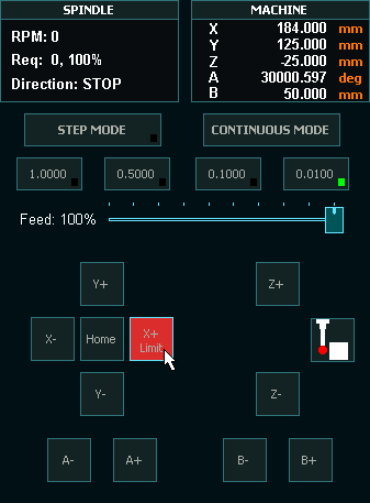
Jogging
- To jog your machine you must be in the F3 Jogging screen.
- Jogging can be done on the F3 screen with either Mouse, Touch screen, Keyboard or Pendant.
- If you cannot Jog use the Mouse to click the jog buttons as users have had issues with faulty Keyboards, pendants and touch screens in the past. Using the mouse is the best test for jogging.
Hint: If the Axis DRO is not showing movement then the physical axis will not move. Please check your Axis settings above and especially your minimum and maximum travel values. If you reach a travel limit the button will turn red and the word Limit will be displayed on the button to let you know.
Hint: If your axis does not move check that you do not have a value of 0 in any of the following settings: Motor: Distance per revolution, Drive: Pulses per revolution, Maximum feedrate or Acceleration. Leaving a value of 0 in any of these 4 parameters on any axis will cause issues. If you are not using an axis please configure it with dummy values.
Pendant
No software configuration is required to make the MASSO MPG pendant work. Simply plug it in and it will work. To make the Estop button on the pendant work you need to wire the Estop in accordance with the Estop Instructions as per the below links. Once the Estop is wired through the pendant, removing the pendant will cause the E-Stop alarm and you will need to plug it back in to remove the Estop condition.
MPG pendant wiring instructions
Wiring only one e stop on MPG pendant instructions
Hint: The biggest problem new users have with pendants come from using 3rd party pendants with incompatible MPG's built into them. They may look the same but internally they use different components. The MASSO Pendant can be purchased from here: MASSO MPG pendant
Hint: MASSO cannot use USB pendants of any type.
Homing Switches and setting up homing
- These can be mechanical, optical, magnetic or proximity sensors.
- Each axis must have a homing switch including software slaved axis which are used for auto squaring.
- The one thing they all have in common is they must normally show Low on the F1 screen and change to High when triggered. Use the spacebar to toggle the input logic if yours is reversed.
Hint: If homing speed is too high the axis may overshoot the sensor and not be able to back off. If the sensor cannot be cleared within 10mm or 3/8” a homing alarm will indicate.
Additional resource video
Hard Limits
The homing inputs double as hard limit inputs after the machine has been homed. To work, all hard limit switches must be outside the envelope of axis travel or the hard limit will trip before it reaches the full travel of your axis. Soft limits should be used first and Hard limits as a last resort. Tripping a hard limit will not instantly stop the axis but it will decelerate to a stop. Hard limits can be disabled under general settings.
Hint: if you mount your homing sensors/switch on the moving carriage and put a trigger at each end of the axis travel then only one sensor/switch can work for both homing and Hard limit triggering at each end of the axis travel.
Soft Limits
- Setting up soft limits is important to prevent your machine from crashing due to gcode command that might result in motion outside your machines physical limits.
- Set up incorrectly it will restrict machine travel and in extreme cases prevent the machine from moving at all.
Minimum and maximum travel setup instructions
Additional resource video
Auto Tool Zero
This feature is used to automatically calculate and adjust the length of each tool. MASSO takes a measurement when you home your machine and will return to the touch off point when a tool change is requested.
Please note that the thickness of the auto tool zero touch off is irrelevant as it is a reference point only. It uses the difference between where you zero your cutter and the initial measurement it took when homing to determine the length of each tool when making a tool change.
CAUTION: Never change a tool after you have homed your machine unless instructed to do so by MASSO. If you must change a tool without MASSO requesting it then do it before homing or home your machine immediately after to get a new reference. Otherwise your next tool change and all the ones that follow will be wrong.
Automatic tool length setup instructions
Additional resource video
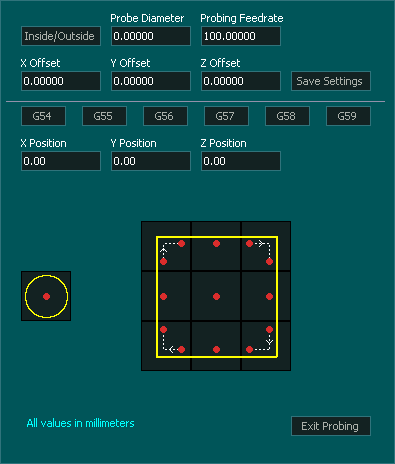
Probing
This document only covers Z height probing though there are many more probing routines built into MASSO. Z height probing can be done with either inside or outside probing screens.
- For probing your Z height enter the thickness of your touch off plate into Z Offset.
- If using a probing tool, Z offset is zero and you enter a value into the Probe diameter.
- Set a Probing feed rate and enter click save settings.
- Probe by clicking the center square.

- Once probing is complete MASSO will automatically update the DRO with the new value.
Hint: If you want to reference your cutter to the surface of the spoilboard you can enter the negative of the nominal material thickness into Set Z and it will work everything out for you. eg for 18mm material enter -18 onto Set Z.

Controlling Spindle using a VFD
WARNING: Please exercise extreme care when setting up your VFD and Spindle. These are not toys and can lead to injury or death if not handled correctly. If you have any doubt contact a suitably qualified electrical technician to assist with your installation. VFD's are complex devices that MUST be installed by a certified person and treated with respect not only because they contain High voltages but also because incorrect configuration of a VFD can destroy both the VFD and the Spindle.
There are various VFD connection examples (provided as a reference only) within the documentation, please note that it is not practical to provide examples of every VFD model and please see the one that suits your VFD model.
- MASSO provides a 0-10v signal to control spindle speed (RPM).
- Two open collector optical switches for forward (clockwise) and reverse (counter-clockwise) signals.
HINT: The biggest issue that users have following the VFD install video is they ignore the first instruction of the video to follow all of the steps. Some steps may seem unnecessary like setting the VFD to work manually but this is one of the most important. If you cannot get it to work manually with simple on/off switches and a potentiometer it will not work when connected to MASSO no matter what you do. As tempting as it is to connect everything at once, please do it step at a time and test as you go. Doing this can take a few extra minutes but can save you hours or days of work figuring out what is wrong.
HINT: The Spindle will not turn unless you issue a speed for it to run at. eg S10000 and a M3 or M4 command.