

 Spanish
  French
  German
  Simplified Chinese
 Setup MASSO Plasma
Quick Start Guide MASSO-G3 Plasma Configuration
These notes have been created to assist new users to set up key configuration properties in MASSO Plasma.
This is not a full configuration guide but seeks to provide configuration guidance. Some items need to be configured in the correct order or things will not work as expected. It will also point out common pitfalls and hints for first time users. I understand that users are keen to see things moving as quickly as possible but usually going slowly and carefully is far quicker than rushing ahead. This does not seek to show how to connect the various hardware that you will connect to MASSO Plasma but will point to various references to assist.
INFORMATION: MASSO Plasma does not have a THC built in to it. For more information see the section below on MASSO DTHC installation
Getting Started
To configure MASSO you first need to connect a minimum of Power supply, Monitor, Keyboard and mouse. Ideally you would also connect your Estop Switch, drives, limit switches, auto touch off, and VFD though you can connect these as you configure each of these components.
Download your Software
Power
Please note that a 1 amp fuse must be connected in the feed from your Power supply on the MASSO G3.
The accidental short circuiting of the auxiliary power terminals built into MASSO will cause damage to the main board if the fuse is not installed.
Safe working Practices when wiring MASSO
Load your Software
Loading software into MASSO Touch Instruction
Additional resource video
Default Password
The default User and Admin password for MASSO is HTG.
Follow the link below to see how to change these passwords.
Estop Switch
An Estop switch is important and MASSO will not work without one. Please ensure you have your Estop connected.
Hint: How the Estop switch is wired will depend on whether you have a pendant or not.
Hint: When Estop is pressed the axis will decelerate to a stop. If an instant stop is wanted on your drives you need to wire the drive’s enable circuit through an Estop Relay contact. A TTL output called ES is provided to allow you to connect a TTL relay which will release when the Estop is pressed. This can be used to stop external hardware. eg. VFD disable, disable motor drives etc.
Additional Resource video
Axis Wiring
How you wire your motors will depend on the type of motors you have.
The link below gives examples of wiring for various motor types, Stepper and Servo
https://docs.masso.com.au/wiring-and-setup/setup-and-calibration/axis-servo-stepper-examples
Additional resource video
Axis configuration
Distance per revolution: How far your axis travels in one revolution of the motor.
Pulses per revolution: How many steps it will take for your motor to complete 1 revolution
Maximum feedrate: Defines your axis rapid speed.
Acceleration setting: Determines how quickly your axis accelerates to your chosen feedrate.
Travel Minimum: This value determines the extent of travel for the axis in the negative direction
Travel Maximum: This value determines the extent of travel for the axis in the positive direction
Invert direction: If your axis travels in the wrong direction, put a check in this box to reverse it.
Backlash: Enter your axis backlash. Note that it must not exceed 10mm or 0.3937”
Hint: The biggest mistake new users make is to ignore the maximum and minimum travel setting. If you leave these at 0 your axis will not move as these form part of Masso soft limit system. Please note that disabling soft limits under general settings only disables them while machining but you are still bound by them when it comes to jogging your axis. It is recommended that you enter very large maximum and minimum values into your axis until you are ready to properly configure them. That way you will be able to jog around your table without running into a limit. The Maximum travel MUST be larger than the Minimum travel value or the axis will move in one direction only.
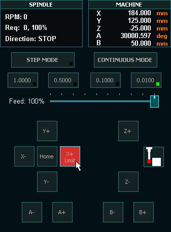
Jogging
To jog your machine you must be in the F3 Jogging screen.
Jogging can be done on the F3 screen with either Mouse, Touch screen, Keyboard or Pendant.
If you cannot Jog use the Mouse to click the jog buttons as users have had issues with faulty Keyboards, pendants and touch screens in the past. Using the mouse is the best test for jogging.
Hint: If the Axis DRO is not showing movement then the physical axis will not move. Please check your Axis settings above and especially your maximum and minimum travel. If you reach a travel limit the button will turn red and the word limit will be displayed on the button to let you know.
Hint: If your axis does not move check that you do not have a value of 0 in any of the following settings: Motor: Distance per revolution, Drive: Pulses per revolution, Maximum feedrate or Acceleration. Leaving a value of 0 in any of these 4 parameters on any axis will cause issues. If you are not using an axis please configure it with dummy values.
Pendant
Wiring only one e stop on MPG pendant
No software configuration is required to make the MASSO Pendant work. Simply plug it in and it will work. To make the Estop button on the pendant work you need to wire the Estop in accordance with the Estop Instructions. See above. Once the Estop is wired through the pendant removing the pendant will cause MASSO to Estop and you will need to plug it back in to remove the Estop condition.
Hint: The biggest problem new users have with Pendants come from using 3rd party pendants with incompatible MPG's built into them. They may look the same but internally they use different components. The MASSO Pendant can be purchased from here:
Hint: MASSO cannot use USB pendants of any type.
Homing Switches and setting up homing
These can be Mechanical, optical, magnetic or proximity sensors.
Each axis must have a homing switch including software slaved axis which are used for auto squaring.
The one thing they all have in common is they must normally show Low on the F1 screen and change to High when triggered. Use the spacebar to toggle the input logic if yours is reversed.
Hint: If homing speed is too high the axis may overshoot the sensor and not be able to back off. If the sensor cannot be cleared within 10mm or 3/8” a homing alarm will indicate.
Additional resources
Homing Sensor Quick Start Guide
Hard Limits
The homing switches double as hard limit switches. To work all hard limit switches must be outside the envelope of axis travel or the hard limit will trip before it reaches the full travel of your axis. Soft limits should be used first and Hard limits as a last resort. Tripping a hard limit will not instantly stop the axis but it will decelerate to a stop. Hard limits can be disabled under general settings.
Hint: if you mount your Homing switch on the moving carriage and put a trigger at each end of the axis travel the one sensor can be both homing switch and limit switch triggering at each end of the axis travel.
Soft Limits
Setting up soft limits is important to prevent your machine from crashing at the extremes of travel.
Set up incorrectly it will restrict machine travel and in extreme cases prevent the machine from moving at all.
Additional resource video
Probing
A big part of running your Plasma will include Probing to set the torch height above the material.
You can find how to connect your torch touch here:
Torch Touch (floating head) Signal
For Probing cycles G38.2 is used from within your Gcode to set your torch height.
Jump to Line
INFORMATION: When using the Jump to line MASSO will search backwards in the Gcode file to locate the last M5 command and use this as it's starting line. If the line you have selected is an M5 command it will use that line. If there is no previous M5 command it will return to the start of the Gcode file.
Torch Breakaway
The torch breakaway signal is used to stop plasma and machine axis movements if the plasma torch is hit during a cut.
Details of the torch breakaway signal can be found here:
Torch On / Off
An input can be designated Plasma On / Off and is used to start and stop the Plasma.
You can configure any of the MASSO G3 TTL outputs as the Plasma on/off and connect it to your Plasma via the MASSO Relay Module
More information on connect your Plasma on/off can be found here:
MASSO DTHC
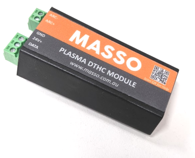
The MASSO DTHC (Digital Torch Height Control) module is designed to provide digital arc voltage information from a plasma source. The module is designed to connect between the MASSO G3 controller and the plasma source with an arc voltage divider output option.
The digital arc voltage data is used by MASSO to monitor arc voltage levels and to adjust the torch height while cutting parts. Having full digital information about arc voltages, the user can easily set and adjust cutting voltages for jobs using gcode commands, this makes it very flexible and easy for the user to set all the cutting parameters of a job in a gcode file, there is no requirement to set cutting voltages manually on an external THC, everything is automatically loaded in when the gcode file is loaded.
INFORMATION: The DTHC module is only supported with the MASSO G3 controllers as the old G2 model does not have the required interface electronics.