

 Spanish
  French
  German
  Simplified Chinese
 Auto Levelling using G38.6
About Auto Levelling
Auto leveling allows you to map the surface of your material and then by probing the surface using the G38.6 digitizing probing cycle and then applying the resulting height map to adjust your original Gcode file.
This is done using 3rd party software such as AutolevellerAE
This is an open source software that can be used to generate the Gcode file to do the initial probing of the material and then the resultant MASSO Probe data.txt file can be loaded in to the software along with your project Gcode file to create a new Gcode file with the coordinates adjusted to suit the material surface.
AutolevellerAE can be down loaded here: http://www.autoleveller.co.uk
The following does not seek to teach you how to use this Auto Leveller software but how to set up the custom parameters to use it with MASSO.
MASSO has no association with this software.
Setting up the Z initialization routine
Under Options menus at the top of the screen select Z initialization routine
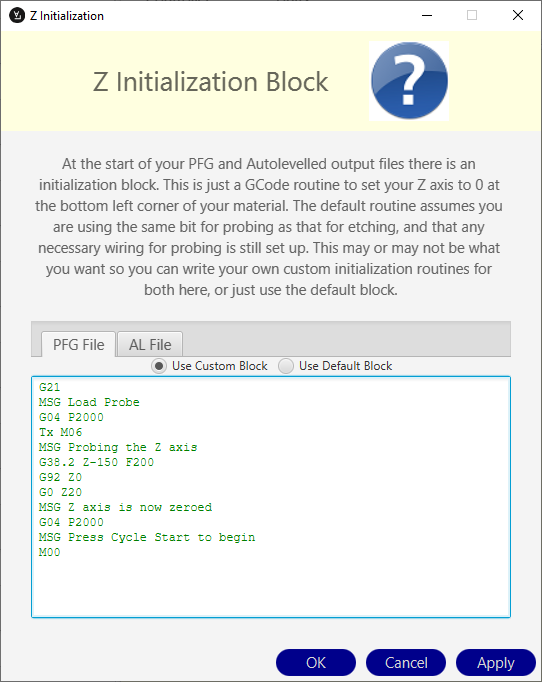
- Under Options menus at the top of the screen select Z initialization routine
- Select Use Custom Block
- Enter your start up routine in here.
In this example
- Machine is set to Metric (G21)
- Message is displayed "Load Probe"
- 2 second delay
- Tool change command to executed.
- Replace Tx with the tool number defined in the F1 screen Touch Probe setting. In the example below the touch probe is Tool 0 so you would replace Tx M06 with T0 M06
- Message is displayed "Probing the Z axis"
- The Z axis probes down to the surface at 200mm/min. When the probe touches the surface it stops. (You may need to change the Z-150 value to suit your machine. The Z value in the G38.2 probing cycle is a Machine Coordinate)
- The Z axis coordinates are set to Z0 using G92 temporary work offset.
- The Z axis moves 20mm up from the surface to Z20
- Message is displayed "Z axis is now zeroed"
- 2 second delay
- Message is displayed "Press Cycle Start to begin"
- M00 Program stop and wait for cycle start.
- After you have a entered your initialization Gcode press Apply followed by OK
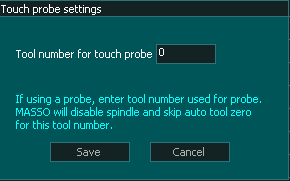
INFORMATION: It is important to define a touch probe tool and use this tool while probing even if you do not have an auto tool changer. The Touch Probe tool disables the spindle while it is selected and is an important safety feature
Custom Z Initialization Block
Please change to suit your machine.
This routine will automatically change your tool to the Probing tool and will automatically use the G38.2 probing routine to zero the Z axis to the correct starting height.
G21
MSG Load Probe
G04 P2000
Tx M06
MSG Probing the Z axis
G38.2 Z-150 F200
G92 Z0
G0 Z20
MSG Z axis now zeroed
G04 P2000
MSG Press Cycle Start to begin
M00
INFORMATION: The auto zero probing routine uses G92 to set Z zero. If you stop the file before it finishes you can remove the temporary work offset by going to MDI and issue a G92.1
Custom Controller Options
From the Options Menu at the top of the screen select Custom Controller Options
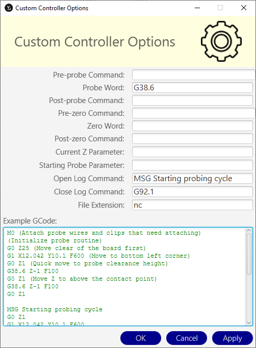
- From the Options Menu at the top of the screen select Custom Controller Options
- Probe Word: G38.6
- Open Log Command: MSG Probing Complete
- Close Log Command: G92.1
- File Extension: Enter nc
INFORMATION: If you have values showing in the parameter fields that are grayed out they can be ignored.
Create a Probing Mesh
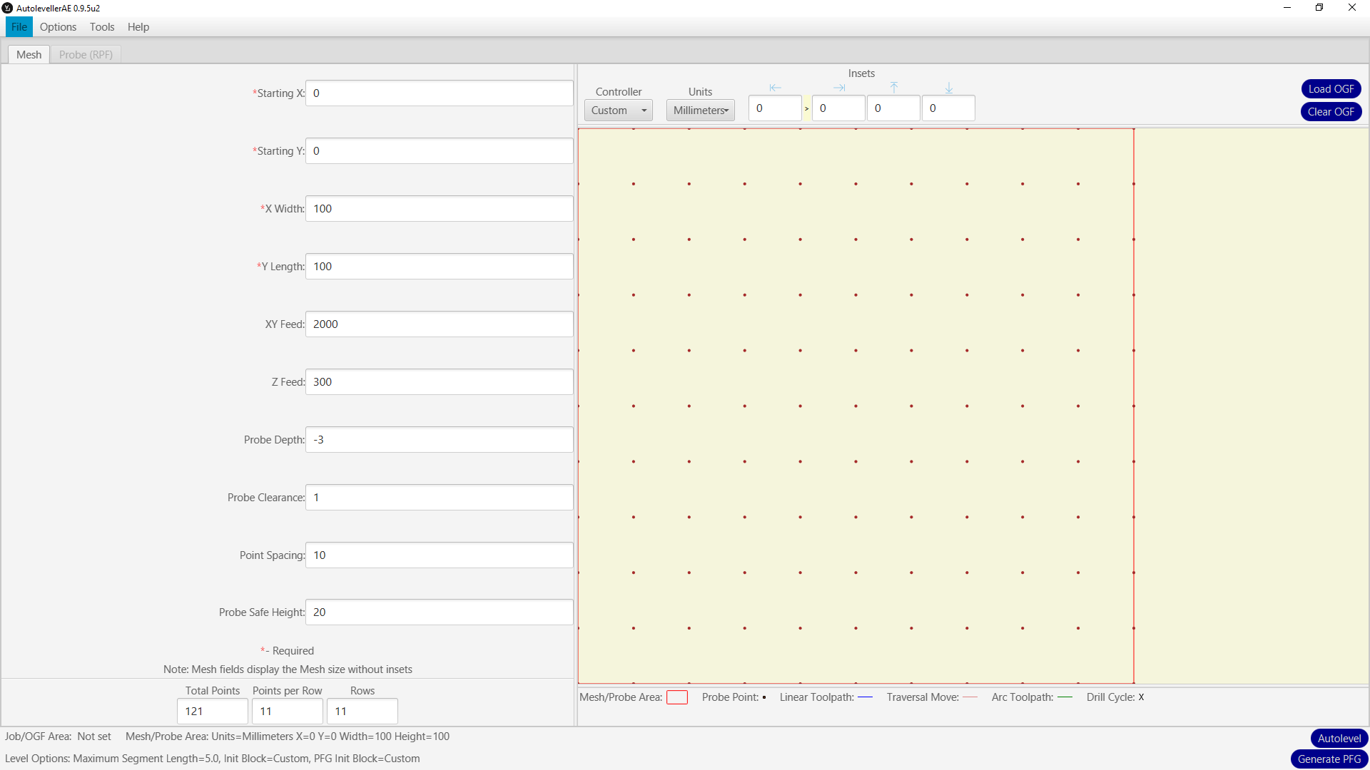
- Starting X: Enter the X working coordinate you wish to start probing from.
- Starting Y: Enter the Y working coordinate you wish to start probing from.
- X Width: Enter the X working coordinate you wish to finish probing.
- Y Length: Enter the Y working coordinate you wish to finish probing.
- XY Feed: Enter the feed rate you wish to travel between probing locations.
- Z Feed: Enter the feed rate you wish to prove the Z axis.
- Probe Depth: Enter the Z axis working coordinate for the end of probing. This is the depth that probing will stop and a "Probing error at:" entry is made in the "MASSO Probe data.txt" file before moving to the next coordinate.
- Probe Clearance: Enter the Z height working coordinate that the Z axis will rise up to after each probe. If you make this too high probing will take longer than needed and if you make it too low you may hit the part while moving to the next probing position.
- Point Spacing: Enter the distance between the probing locations.
- Probe Safe Height: This is used at the end of the probing cycle to rise the Z axis above the surface.
Once you are happy with the parameters press Generate PFG to create the probing Gcode file.
INFORMATION: This software can also be used to create cloud point captures of 3D objects using the same process. Select a point spacing that suits the item you are probing. A finer Point Spacing will render a more detailed data capture which you can pass to other software for rendering to a 3D model.
Create an Auto Leveled file
Basic overview
- Load your Gcode file Called OGF in the software.
- Load the Captured MASSO Probe Data.txt File saved to your MASSO Flash drive under the File Menu Raw Data File (RPF)
- Adjust parameters as needed. Please see the Autoleveller software manual for full details on how to use this aspect of the software.
- Press Autolevel to generate adjusted Gcode file to run on MASSO.
WARNING: The incorrect use of this Gcode can cause damage to your probing equipment, the item being probed and personal injury. Please understand and exercise care.