G92 – Temporary Work Offset
This command is used set temporary work offset values. The temporary work offsets are used in combination to the main work offsets G54 to G59.
Applying a temporary work offset to an axis will change the working coordinate of the axis to the specified value.
When a temporary work offset is applied it is shown on the F2 screen as the current work offset + G92 
A temporary work offset is applied to all work offsets G54 to G59 until cancelled.
Syntax & Parameters
- G92 followed by axis values.
- X, Y, Z, A, B Value - specifies the axis you wish to offset and the new working DRO value
INFORMATION: G92 work offsets are be cancelled by G92.1
Example program
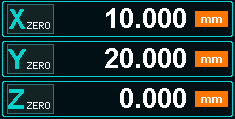
N10 G92 X10 Y20
In this example the X and Y axis will not move and a temporary work offset will be applied the the X & Y axis.
The X axis working DRO will display 10 and the Y axis working DRO will display 20.
The amount of the offset is automatically calculated to give the required working coordinate.
A common use of temporary work offsets is in with probing cycles such as setting the torch height in Plasma
N10 G38.2 Z-50
N20 G92 Z0
N30 G0 Z1
In this example the G38.2 probes Z axis toward the surface of the material and when the touch input is triggered it will stop
The G92 Z0 sets the working coordinate to Z0
G0 Z1 moves the Z axis 1 unit above the material surface.
INFORMATION: Units are defined as either inches or mm depending on your machines setup or G20 or G21 command in use.
Zeroing Axis with Temporary Work Offsets Applied
- DRO's with Temporary work offsets cannot be zeroed by pressing the X, Y or Z Zero buttons on the DRO.
- When a G92 work offset is applied to an axis and the DRO is zeroed the offset value will be applied show and on the DRO instead of 0.
- If you click on an axis DRO with a Temporary Work Offset applied and enter a new value, the Temporary Work Offset value will be applied to it and a new working coordinate will be displayed.
- Use G92.1 to cancel the temporary work offset.


 Spanish
  French
  German
  Simplified Chinese