Spanish
  French
  German
  Simplified Chinese
 Checking Optocouplers
If any of the optically isolated inputs on the controller do not work then the below steps can be done to find the cause of the problem.
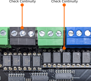
Step 1: Checking ground side continuity
With a multimeter check, the continuity between the black connector and the below-marked pin of the optocoupler input that's not working.
If there is no continuity then it can be caused because of the below reasons:
- The optocoupler is not plugged in properly.
- The track on the circuit board has been damaged.
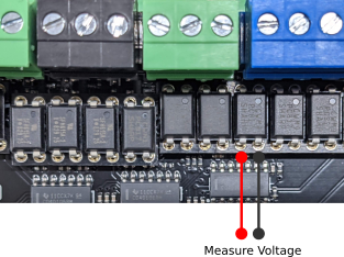
Step 2: Measuring input signal voltage
Connect a 5v to 24v signal to the input that is being tested and measure the voltage on the below-marked points.
This voltage should be around 1.1v. If this voltage is not received then it can be caused because of the below reasons:
- The optocoupler is not plugged in properly.
- The track on the circuit board has been damaged.
- The resistor for this optocoupler is damaged.
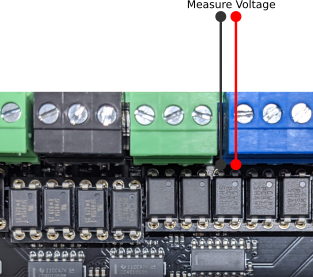
Step 3: Measuring output signal voltage
Ensure that no signal is connected to the input and measure the voltage on the below-marked points.
This voltage should be around 3.1v.
Connect a 5v to 24v signal to the input and measure the voltage on the below-marked points.
This voltage should drop to around 0.14v. If this voltage is not received then it can be caused because of the below reasons:
- The optocoupler is not plugged in properly.
- The optocoupler is damaged.
- The track on the circuit board has been damaged.