

 Spanish
  French
  German
  Simplified Chinese
 Axis Calibration
Once all the electrical connections have been done, the system can be calibrated. Axis calibration can be done in the following simple steps:
Motor: Distance per revolution
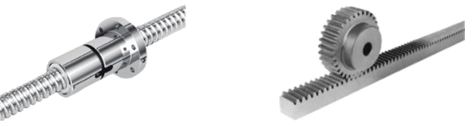
- First note down the pitch of your ball screw. Pitch defines how much the ball nut moves when the ball screw is turned exactly one full rotation.
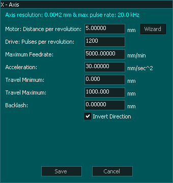
- In the F1-Setup screen, open the axis setup window and enter the ball screw pith in the Motor: Distance per revolution box.
- If the machine axis moves are controlled using timing belts or has a rack and pinion type setup then enter the amount of axis movement when the motor shaft is turned exactly in one full rotation. If this value is unknown or hard to calculate then the calibration wizard can be used which is explained on the bottom of this page.
Drive: Pulses per revolution
Servo and stepper motor drives have either switches or software tools to setup the drives Pulses Per Revolution (PPR) settings. These settings define how many pulses the drive will take to turn the motor shaft one complete revolution.
INFORMATION: Please refer to your motor drives documentation on how to setup PPR.
Maximum Feed Rate
Each machine axis have limitation of maximum allowable speed depending on the hardware and safety limitations. The maximum feed rate value is used to check and make sure that the system does not exceed this value during operation. This value might be different for each axis depending on the design of that axis.
Acceleration
Depending on the moving mass and motor torque the acceleration value can be set for each axis.
Axis Direction
The invert direction tick box is used to reverse the direction of travel of the axis.
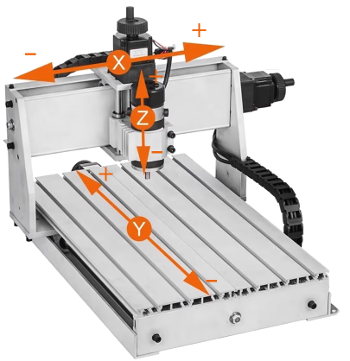
It is critical that before setting maximum and minimum travel or using the calibration wizard that you ensure that the axis is moving in the correct direction.
See the image below for more information
Minimum & Maximum Travel
These values define the travel as well as minimum and maximum values of the axis. In most setups this values is between 0.00 and some positive number, but in some cases such as Z axis of a milling machine this value can be negative as the axis homes towards the top which is 0.00 but the actual machining happens in the negative direction that is towards the machine bed.
NOTE: The minimum and maximum travel also sets the soft limit of the axis and its very important to set this value with the exact travel of the axis.
INFORMATION: If minimum, maximum or homing position (in homing settings window) values are not correctly entered then the axis might not home properly.
Axis Calibration Wizard
If this axis distance per revolution value is unknown or hard to calculate then the Axis Calibration Wizard can be used, please CLICK HERE for details.