Spanish
  French
  German
  Simplified Chinese
 Axis Calibration Wizard
Axis calibration wizard can be used to calibrate axis where the calibration values of the mechanical setup are unknown or hard to calculate axis. This may be due to multiple ratios on the axis such as timing belts and rack & pinion designs.
WARNING: Ensure that your axis are moving in the correct directions before calibrating your machine. For additional information on Axis Direction of travel see HERE
INFORMATION: If your Axis maximum and minimum travel is not set correctly you may not be able to travel the required distance for calibration. In this case change your maximum and minimum travel distances while doing your calibration to ensure you do not reach the limits.
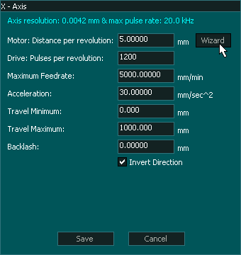
Open the wizard by clicking the "Wizard" button
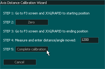
Calibration steps
INFORMATION: For best results, move the axis from one extreme of the axis to the other extreme during calibration, the longer the distance measured during calibration the more accurate the calibration will be.
INFORMATION: Before starting axis calibration ensure that backlash is turned off.
Step 1 Mark the starting point
Ensure that Backlash is turned off.
Go into the F3 Screen and Jog the axis that you wish to calibrate to one end of the axis travel and mark the starting point. This could be as simple as putting a sharp Vbit into your spindle and marking an X under the cutter to show the starting point. Ensure that when you move to the starting point you jog in the same direction of travel that you will be moving in to the end point. This will remove backlash from the axis under test..
INFORMATION: The easiest way to do this is to use a piece on masking tape with an X already marked on it and slide it under the cutter point.
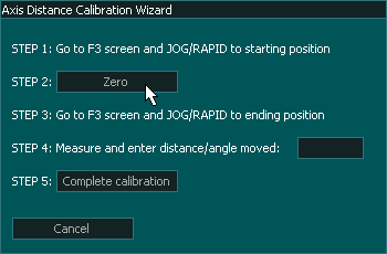
Step 2 Zero the Axis
Return to the F1 Screen and click the "Zero" button on the calibration Wizard screen.
The button will change to read "Zero Set"
Step 3 Move to the end point
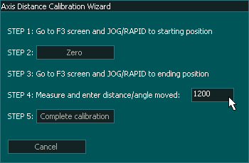
Step 4 Measure
Using a ruler measure the distance between the starting X and the end X.
Enter the measured distance the axis moved into box on the calibration wizard.