Spanish
  French
  German
  Simplified Chinese
 MASSO Closed Loop Stepper Motors
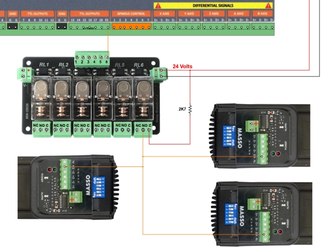
Wiring instructions
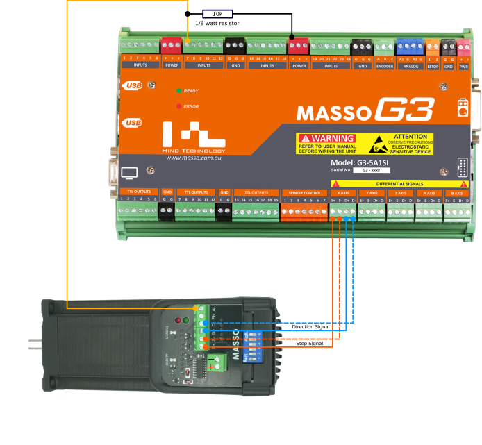
INFORMATION: Use Shielded twisted pairs between MASSO and the Motor for the Step and direction differential signals. This will provide the greatest noise immunity. Ensure that the shield is connected to the ground at the MASSO end only. Do not ground the shield at both ends or you will create a ground loop. AWG 24 (0.2mm²) to AWG 22 (0.3mm²) is suitable for the signal wires. Ensure the wires are multi-stranded and twisted.
Power
The MASSO closed loop stepper motor drive is powered by a 24 to 36 volts DC power supply.
The power connector requires a minimum conductor size of 0.75mm². The power connector terminal will accept a wire up to 1.5mm².
Information: The -ve of the MASSO Power supply and the -ve of the Motor power supply must be connected together to form a common ground or the Enable and Alarm signals will not work correctly. Connect the power supply negatives at the main power distribution point. Do not use the Black GND terminals on MASSO for this purpose.
CAUTION: Observe the correct polarity when connecting the power to the MASSO closed loop stepper motor. Incorrect polarity will damage the drive.
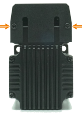
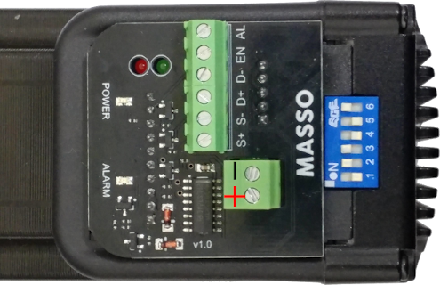
Open the marked rear screws to open cable cover
Connecting the Motor Enable
- To enable the stepper motor a 5 to 24-volt signal is required.
- Normally this would be provided through an Estop relay which would disconnect the signal when the Estop button is pressed.
- It is suggested that this voltage be supplied via a resistor of suitable value as it is only a logic level signal and the resistor will limit fault current in case it accidentally comes into contact with the ground. A 2.7K 1/4 watt resistor is a good choice for this task.
- If the Enable signal does not work check that the Motor power supply and the MASSO power supply share a common ground.
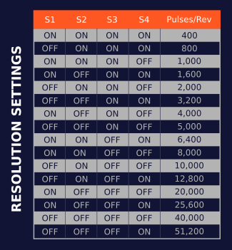
Setting Up Motor Resolution
WARNING: Only change the switch settings when the motor is powered off.
Status LED & Alarms
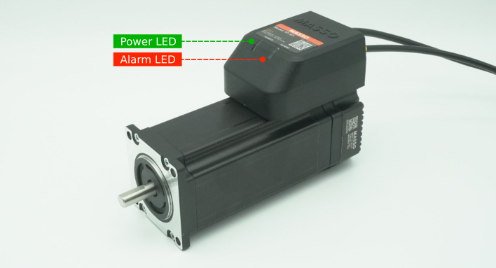
Alarms can be caused by any of the below reasons:
- The enable signal of 5v to 24v is not received by the motor.
- The motor received STEP signals that have acceleration or top RPM higher than the motor can support. This will also be affected by how much load is on the motor.
- The power applied to the motor is less or more than the motor's specifications.
- The current required to work under load is not enough.
- The motor is not able to complete the requested rotation due to external mechanical issues such as the machine axis hitting something or getting stuck.
For additional trouble shooting of the MASSO Closed loop stepper motor please see >>>HERE<<<
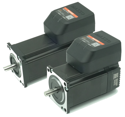
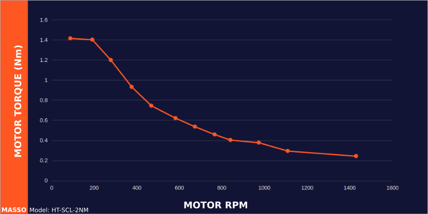
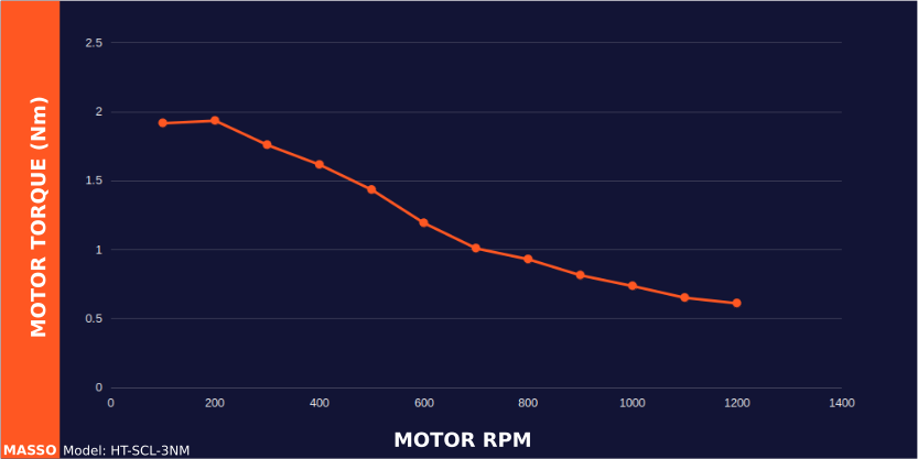
Torque Information
Model: HT-SCL-2NM with 2N·m maximum torque
Model: HT-SCL-3NM with 3N·m maximum torque
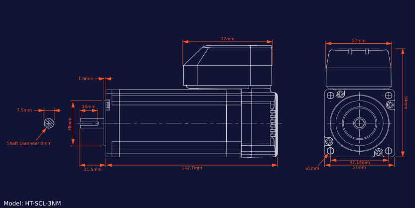
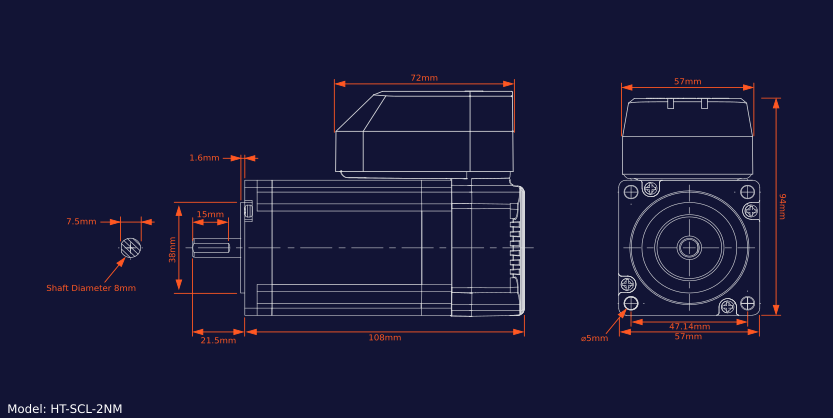
Mechanical Data
Model: HT-SCL-2NM
Model: HT-SCL-3NM