

 Spanish
  French
  German
  Simplified Chinese
 Spindle Control
MASSO provides 0~10v, PWM and STEP/DIR control signals to control a variety of VFD and DC spindle and Servo or stepper drives
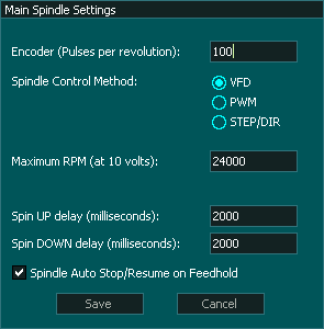
In the Spindle Settings window the mode of spindle control can be selected. Further, Spin UP and Spin DOWN delay values can be added. The spindle delay values pauses the machine on spindle ON and OFF commands for the spindle to get to the required RPM.

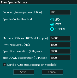
INFORMATION: PWM frequency on the MASSO can be set between 4 kHz to 65 kHz.
INFORMATION: When running in PWM mode MASSO outputs Uni-polar PWM signals.
VFD Control
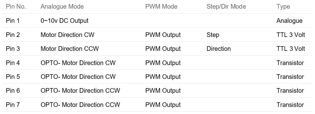
- Spindle control pin1 outputs a 0 to 10 volt analogue voltage proportional to the the required speed
- Spindle Control Pin 2: Is normally LOW and changes to HIGH when the spindle is set to forward
- Spindle control Pins 4 & 5 are normally open circuit and conduct when the spindle is set to forward
- Spindle Control Pin 3: Is normally LOW and changes to HIGH when the spindle is set to reverse
- Spindle control Pins 6 & 7 are normally open circuit and conduct when the spindle is set to reverse
PWM Control
- Spindle Control Pin 2: Outputs a PWM signal when the spindle is set to forward
- Spindle control Pins 4 & 5 Turns on and off with the PWM signal when the spindle is set to forward
- Spindle Control Pin 3: Outputs a PWM signal when the spindle is set to reverse
- Spindle control Pins 6 & 7 Turns on and off with the PWM signal when the spindle is set to reverse
- PWM frequency on the MASSO can be set between 4 kHz to 65 kHz.
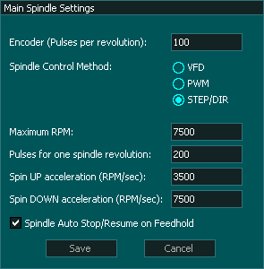
STEP/DIR control
Using a Stepper motor or Servo as a spindle
- The Step and direction mode outputs are Common GND signals.
- Spindle Control Pin 2: Step
- Spindle Control Pin 3: Direction
- Minimum Step rate 500 pulses per second or 150rpm if using a 200 step per revolution motor with micro step rate of 1.
- Maximum pulse rate: 25000 pulses per second or 7500rpm if using a 200 step per revolution motor with micro step rate of 1.
- Increasing the micro step on your motor drive will reduce both the minimum and maximum spindle speed.
- If the requested speed is below the minimum speed, the spindle will run at the minimum speed of 500 pulses per second.
- If the requested speed is above the maximum speed, the spindle will run at the maximum speed of 25000 pulses per second.
Spindle Auto Stop / Resume on Feedhold
- When this option is ticked the spindle will stop on Feed hold and and when Cycle start is pressed to resume machining the spindle will automatically restart before machining connences.
- If this option is not ticked a feed hold will not stop the spindle and the user will need to manually stop it if required. Before resuming machining the user will need to restart the spindle before pressing Cycle Start.
For information on wiring of the spindle control to your VFD please see our Spindle VFD examples page.
For troubleshooting a VFD / Spindle problem please see this Troubleshooting guide