

 Spanish
  French
  German
  Simplified Chinese
 Spindle RPM Encoder
An incremental encoder is used to monitor spindle RPM and also for synchronized threading on lathes.

Spindle Encoder Signal
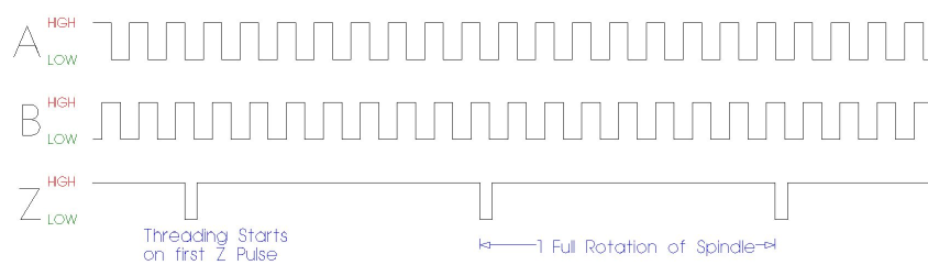
MASSO Spindle Encoder turning in slow motion
INFORMATION: The maximum pulse frequency on encoder inputs for MASSO G3 controllers is 60kHz.
INFORMATION: The maximum pulse frequency on encoder inputs for MASSO G2 controllers is 8Khz
INFORMATION: The MASSO G2 can be modified to 20Khz by changing 3 Optocouplers and removing some capacitors.
Upgrading the Spindle encoder on MASSO G2
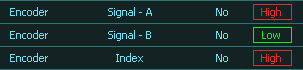
INFORMATION: All input signals can be easily inverted by selecting the input in the INPUTS list and pressing the space-bar key on the keyboard to invert the input signal. These settings are automatically saved.
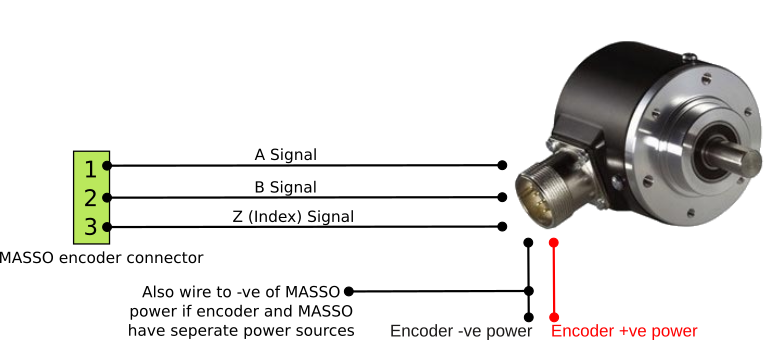
Voltage output signal wiring example
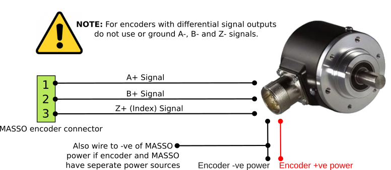
Differential / Line Driver output signal wiring example
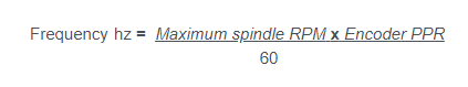
Maximum Encoder Frequency
Spindle speed Encoder for Mill
To see the actual RPM of your Spindle you must to use an encoder.
Speed signals taken direct from the VFD indicate the requested spindle speed it receives from MASSO and not the actual spindle speed
If you do not have an encoder installed on your spindle but wish to see a speed indication on the F2 screen, setting the Encoder (Pulses per revolution) value to 0 will show the speed sent to the VFD.
If your Spindle includes a pulsed output or you have an external encoder, you can connect this to the A spindle encoder input of your G3.
MASSO can use this to display the spindle speed.
In the Main Spindle set up page in the F1 screen enter the encoder pulse per revolution output by your spindle.
The spindle encoder inputs are optically isolated like the rest of MASSO inputs. You need to have the pulse signal referenced to MASSO ground as with all input signals.
