INFORMATION: This tool changer logic is only available on MASSO G3 controllers running software version 5.0 and above.
WARNING: Please exercise great care when setting the tool changer parameters as incorrect settings may produce strange results and cause damage to your tool changer. If you are at all unsure about your settings you may find it useful to use feed rate override to slow the machine down while you are setting it up. Feed override
INFORMATION: Tool Changers may be placed outside of soft Limits to protect them from accidental damage however the Auto Tool Zero must remain within soft limits.
Introduction
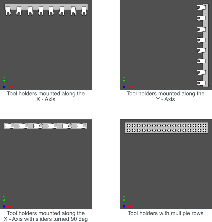
The linear tool changer logic allows multiple types of linear tool changer setups to be easily configured. Each tool can be positioned independently giving the user the option to have tools in single or multiple rows.
Below are some common examples:
Setup process
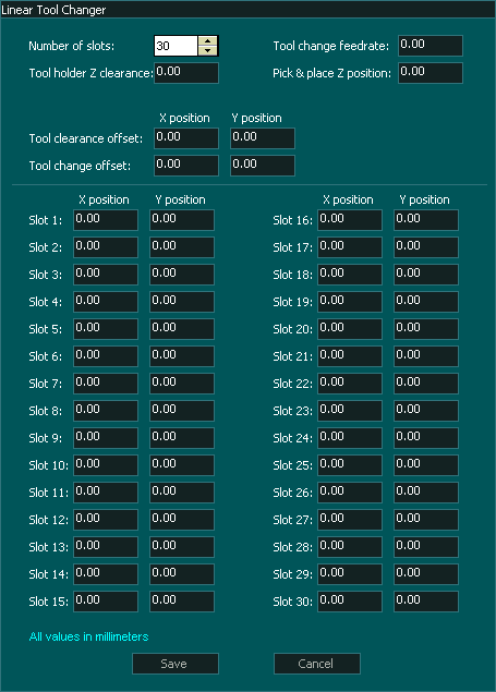
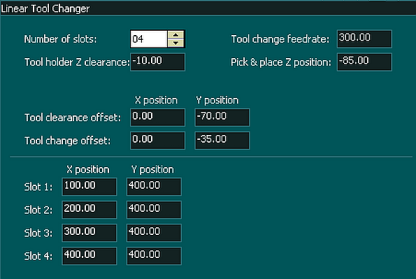
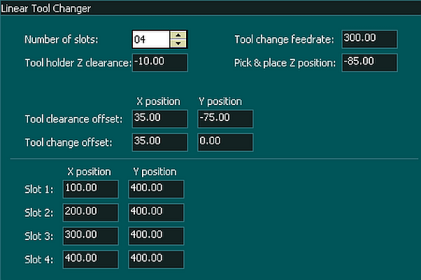
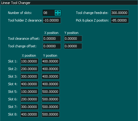
The below window shows all the parameters that are required to set up the tool changer logic.
Assigning the number of slots
- The Linear tool changer allows for up to 30 tool slots to be assigned. When you first open the Linear Tool Changer page you will see 4 slots displayed.
- To increase or decrease the number of slots displayed for your tool changer use the up and down arrows beside the Number of slots: box to change the value.
Tool Change Feedrate
- This parameter defines the feed rate that is used to slide a tool into and out of a tool holder.
- The feed rate is defined in the native unit of measurement, either metric or imperial that you have set under general settings in the F1 Screen.
- The Distance that a tool slides in and out is defined by the Tool Change offset.
- All other movements are performed at rapid speeds.
Tool holder Z clearance
- This parameter defines the position that the Z axis will move to when it has dropped the old tool into its slot and is traveling to the new slot to pick up the new tool.
- The Z clearance height is a machine coordinate.
- Travel between tools will be at rapid speed.
- Travel will take the most direct route to the next tool to be picked up and may travel across the top of other tool holders.
Pick & place Z Position
- This parameter defines the height of the Z axis as a tool slides into or out of a tool holder.
- This parameter defines the height the Z axis descends to when picking up or dropping off a tool in a pick and place tool changer.
- The Z position height is defined as a machine coordinate.
- The Z-axis moves at rapid speed when rising up from or dropping onto a tool.
Tool Clearance Offset
- This parameter defines where the spindle will move to begin the tool change process.
- The position is defined by X & Y coordinates and these are relative coordinate values that will be added to the slot position coordinate value.
- You can use positive or negative values to determine which side of the tool holder you approach from.
- The values are defined in the native unit of measurement, either metric or imperial that you have set under general settings in the F1 Screen.
- Once the spindle has moved to the Tool clearance offset position it will rapid toward the Tool change offset position
- The Tool clearance offset is only used at the start of the tool change process before dropping off the old tool.
Tool change offset
- This parameter defines the position where the spindle will begin the slide into or out of the tool slot.
- The feed rate used for the slide in the process is defined by the Tool Change feed rate parameter
- On a sliding tool change usually only one of the position values will be used and the other is left at 0. If both X & Y positions have defined values the tool will enter the slot at an angle.
- On a Pick and place tool changer this parameter must be set to X0, Y0.
- The position is defined by X & Y coordinates and these are relative coordinate values that will be added to the slot position coordinate value.
- You can use positive or negative values to determine which side of the tool holder you approach from.
- The values are defined in the native unit of measurement, either metric or imperial that you have set under general settings in the F1 Screen.
Defining the Tool Position
- The Center of each slot is defined by the Slot #: X, Y position parameter box.
- These coordinates are used to define the tool position and are Machine coordinates.
- The values are defined in the native unit of measurement, either metric or imperial that you have set under general settings in the F1 Screen.
- Because each tool holder's position is defined by both an X & Y coordinate you can place the tools anywhere on the table.
- When using a Pick and place tool holder you can define multiple rows of tools.
INFORMATION: Tool slot coordinates can be located outside of the machine's soft limits.
Coordinate Calculations
Calculate coordinate positions as follows:
- Tool clearance offset coordinate X, Y = Slot position X + Tool clearance offset position X, Slot position Y + Tool clearance offset position Y
- Tool change offset coordinate X, Y = Slot position X + Tool change offset position X, Slot position Y + Tool change offset position Y
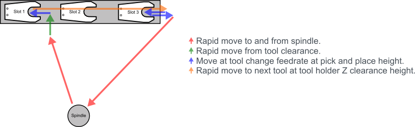
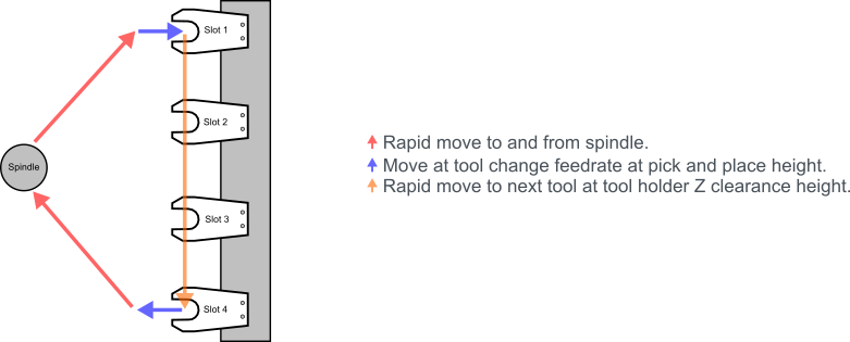
Example: 1 
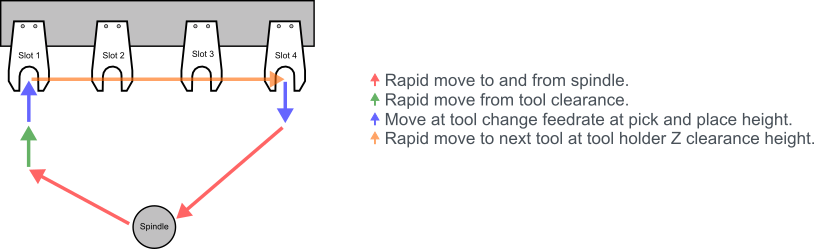
- In the following example Tool 1 is in Slot1 and Tool 2 is in Slot 4
- Current tool loaded Tool 1
- Gcode T2 M06
- Spindle rapids to Machine coordinate X100 Y330 (Tool clearance offset coordinate)
- Rapid move to Machine coordinate X100 Y365 (Tool Change offset coordinate)
- Move at feed rate 300mm/m at a Machine coordinate Z height of Z-85 to X100 Y400 (Slot 1 Coordinate)
- Chuck clamp released and Z rises to Machine coordinate Z-10
- Rapid move to X400 Y400 (Slot 4 Coordinate)
- Z descends to Z-85 and chuck clamp locks
- Move at feed rate 300mm/m at a Machine coordinate Z height of Z-85 to X400 Y365 (Tool Change offset coordinate)
- Z-axis ascends maximum height and rapids to original spindle position
- Machining resumes.
Example: 2 
- In the following example Tool 1 is in Slot 1 and Tool 2 is in Slot 3
- Current tool loaded Tool 1
- Gcode T2 M06
- Spindle rapids to Machine coordinate X135 Y325 (Tool clearance offset coordinate)
- Rapid move to Machine coordinate X135 Y400 (Tool Change offset coordinate)
- Move at feed rate 300mm/m at a Machine coordinate Z height of Z-85 to X100 Y400 (Slot 1 Coordinate)
- Chuck clamp released and Z rises to Machine coordinate Z-10
- Rapid move to X300 Y400 (Slot 3 Coordinate)
- Z descends to Z-85 and chuck clamp locks
- Move at feed rate 300mm/m at a Machine coordinate Z height of Z-85 to X335 Y400 (Tool Change offset coordinate)
- Z-axis ascends maximum height and rapids to original spindle position
- Machining resumes.
Example: 3 
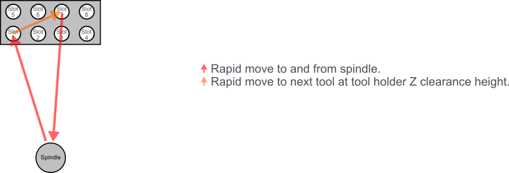
- In the following example Tool 1 is in Slot 1 and Tool 2 is in Slot 7
- Current tool loaded Tool 1
- Gcode T2 M06
- Spindle rapids to Machine coordinate X100 Y400 at Z maximum Z height (Tool slot1)
- Tool moves down to Z-85 and Chuck clamp releases tool (Pick & place Z position)
- Chuck clamp released and Z rises to Machine coordinate Z-10 (Tool Holder Z clearance)
- Rapid move to X300 Y500 (Slot 7 Coordinate)
- Z descends to Z-85 and chuck clamp locks tool in the spindle
- Z-axis ascends maximum height and rapids to original spindle position
- Machining resumes.
Example: 4 
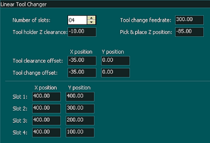
- In the following example Tool 1 is in Slot 1 and Tool 2 is in Slot 4
- Current tool loaded Tool 1
- Gcode T2 M06
- Spindle rapids to Machine coordinate X365 Y400 (Tool clearance / Tool change offset coordinate)
- Because the Tool clearance offset and the Tool change offset are in the same position the next move is the Tool change
- Move at feed rate 300mm/m at a Machine coordinate Z height of Z-85 to X400 Y400 (Slot 1 Coordinate)
- Chuck clamp released and Z rises to Machine coordinate Z-10
- Rapid move to X400 Y200 (Slot 4 Coordinate)
- Z descends to Z-85 and chuck clamp locks
- Move at feed rate 300mm/m at a Machine coordinate Z height of Z-85 to X365 Y200 (Tool Change offset coordinate)
- Z-axis ascends maximum height and rapids to original spindle position
- Machining resumes.
TroubleShooting
- If your tool changer starts the tool change and stops when it get to the slide in part of the tool change check that you have assigned a the Tool Change feed rate as the default of 0 will stop the slide in and out process.


 Spanish
  French
  German
  Simplified Chinese