


 Spanish
  French
  German
  Simplified Chinese
 Linear Tool Changer (Type 1)
Two types of linear tool changers are supported with some different control logic inputs and outputs. Please see both Type 1 and Type 2 logic explanations and see the one that fits best to your machine requirements.
Selecting the tool changer
In the Tool Changer window select Linear Tool Changer (Type 1) and double-click for settings.
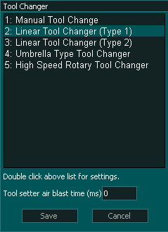
INFORMATION: The Tool setter air blast is used to clean dust from the tool setter after the tool has been changed and before the tool is measured. It is not used during the tool change process.
Setting up the tool changer logic
Tool Changer Inputs and Outputs
Syntax used in this document for Tool Changer inputs and outputs
"Tool Changer - Output 1" means Tool Change - 1 and it is an output
"Tool Changer - Input 1" means Tool Changer -1 and it is an Input
Note: Any tool changer input or output can be assigned to any Input or Output on MASSO. The tool changer number does not refer to an actual input or output port.
INFORMATION: If your machine does not have a sensor for one or more of the inputs below then do not assign an input to that function and the tool change logic will ignore the input and will continue.
INPUTS
- Tool Changer - Input 1 for Spindle drawbar Status (Low for clamped and High for un-clamped)
- Tool Changer - Input 2 for Dust Hood UP OK signal
- Tool Changer - Input 3 for Dust Hood DOWN OK signal
- Tool Changer - Input 4 for Tools Tray UP OK signal
- Tool Changer - Input 5 for Tools Tray DOWN OK signal (INFORMATION: If only one sensor for UP/DOWN status is used then do not assign this function to any input, this logic is available in G3 v5.01.12a and above)
OUTPUTS
- Chuck Clamp M10/M11 for spindle drawbar clamp and un-clamp (Low to clamp and High to un-clamp)
- Tool Changer - Output 1 to move Dust Hood UP
- Tool Changer - Output 2 to move Dust Hood DOWN
- Tool Changer - Output 3 to move Tools Tray UP
- Tool Changer - Output 4 to move Tools Tray DOWN (INFORMATION: If only one valve is used for tray UP/DOWN then do not assign this function to any output, this logic is available in G3 v5.01.12a and above)
Tool Changer logic
When a tool change command is received, the tool changer logic works in the followings steps:
- Spindle is turned OFF and the system waits for the spindle to stop as per the spindle "Spin down delay" value in the spindle settings.
- The system checks if the current tool in the spindle is setup in a slot is the F4-Tools screen, else gives an error.
- The system checks if the tool to load is setup in a slot is the F4-Tools screen, else gives an error.
- Z-Axis moves up to the homing position.
- "Tool Changer - Output 1" goes HIGH to move Dust Hood UP, then the system waits for 6 seconds for the "Tool Changer - Input 2" (Dust Hood UP OK) signal to go HIGH, else gives an error.
- "Tool Changer - Output 1" goes LOW.
- "Tool Changer - Output 3" goes HIGH to move Tools Tray UP, then the system waits for 6 seconds for the "Tool Changer - Input 4" (Tools Tray UP OK) signal to go HIGH, else gives an error.
- "Tool Changer - Output 3" goes LOW.
- X & Y-Axis moves to tool unload position.
- "Chuck Clamp M10/M11" goes HIGH to unclamp the tool, then the system waits for 6 seconds for the "Tool Changer - Input 1" (Spindle draw bar Status) signal to go HIGH, else gives an error.
- X & Y-Axis moves to the new tool load position.
- "Chuck Clamp M10/M11" goes LOW to clamp the tool, then the system waits for 6 seconds for the "Tool Changer - Input 1" (Spindle draw bar Status) signal to go LOW, else gives an error.
- Axis moves to slide out the new tool.
- "Tool Changer - Output 4" goes HIGH to move Tools Tray DOWN, then the system waits for 6 seconds for the "Tool Changer - Input 5" (Tools Tray DOWN OK) signal to go HIGH, else gives an error.
- "Tool Changer - Output 4" goes LOW.
- "Tool Changer - Output 2" goes HIGH to move Dust Hood DOWN, then the system waits for 6 seconds for the "Tool Changer - Input 3" (Dust Hood DOWN OK) signal to go HIGH, else gives an error.
- "Tool Changer - Output 2" goes LOW.
INFORMATION: All input & output signals can be easily inverted by selecting the input or output in the list and pressing the space-bar key on the keyboard to invert the signal. These settings are automatically saved.
INFORMATION: Make sure to assign each tool into a tool slot in the F4 - Tools & Work offset screen else on a tool change command if the tool is not set in a slot you will get a tool error alarm.
INFORMATION: Tool Changers may be placed outside of soft Limits to protect them from accidental damage however the Auto Tool Zero must remain within soft limits.
Tool Numbering
CAUTION: Please be aware that from MASSO G3 software versions 5.0 and higher, user assignable tools have changed and are now Tool 1 to 100.
INFORMATION: Depending on your software version your first user assignable tool will be either Tool 0 or Tool 1

