Spanish
  French
  German
  Simplified Chinese
 Tool Setter
A tool setter or a simple touch plate can be wired to MASSO to be used with interactive part probing or with G38.2 probing cycle gcode command.
INFORMATION: For information about interactive part probing CLICK HERE
INFORMATION: For information about using G38.2 probing cycle CLICK HERE
Wiring example of a simple touch plate
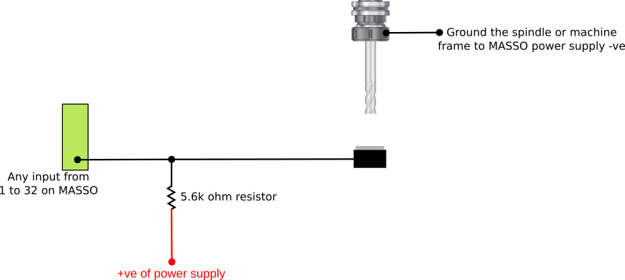
This circuit is of a simple touch plate where the plate and the cutter complete the circuit when they touch.
The pullup resistor used in this circuit pulls the input high and the input logic must be inverted to show low when the tool setter is not triggered.
The pullup resistor should be a minimum of 1/8 watt.
This is done by selecting the input and pressing the spacebar to toggle between High and Low. 
The Resistor and +ve power supply must not left out or the tool setter will not work.
The Resistor must not be replaced with a direct connection to the power supply to the input or you will cause a short circuit when the tool touches the touch off.
Wiring example of a Tool setter with built in switch
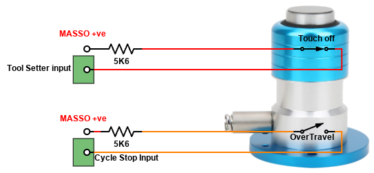
Invert the input as needed to show Low when the tool setter is not active and High when triggered by highlighting the input and pressing the spacebar. 
Tool setters which include include a 2nd switch to detect over travel can be used with the Cycle Stop or wired into the Estop circuit in case the first switch fails. 
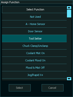
Assigning the Touch plate input
Once the probe has been wired to one of the MASSO inputs, go to the F1 - Setup screen and assign the input as Tool Setter
CAUTION: The input status must show LOW when the Tool setter is not being touched and should only show HIGH when triggered.
INFORMATION: To invert the input signal, invert by selecting the input in the INPUTS list and press the space-bar key on the keyboard. These settings are automatically saved.