There are 8 Corner probing cycles. 4 are inside probing cycles and 4 are Outside probing cycles.
The one you choose will be determined by whether you are probing the inside or the outside of a part
When entering new values or changing between inside and outside remember to press the Save button to make the new values or selection active
First select Inside or outside by pressing the Inside/Outside button on the probing cycles screen 
Next press the Save settings button to complete the change 
X & Y offsets can be used to compensate for errors or offset the probe from the Spindle because it is in a position different from the spindle. 
Each corner probing button shows a dotted white line indicating the order in which probing will take place.
The X & Y Position boxes are used to define the working coordinate of the surface at the point of touch. 

The probing cycle can be stopped by pressing the same or a different probing cycle button.
As of Software version 5.0 and above the user can select which Work offset the probe result will be applied to by selecting a appropriate work offset button before starting the probing cycle. Please be aware that only the selected work offset will be updated. 
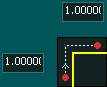
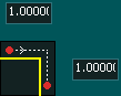
Inside Corner Probing
- The Red dot indicates the position of the probe at the start of the probing cycle and the probe will move towards the Yellow line which represents the object being probed.
- The dotted white line indicating the order in which probing will take place.
- Each probing cycle is an automatic two part probing cycle.
- The probing will occur at the speed entered in the Probing Feedrate box

- After touch off the Axis will return to the start position at rapid speed.
- Enter the Probe diameter into the Probe Diameter box


The probe will start moving in the -X direction at the specified Probing feed rate until it touches the part.
The Probe will return to its start position.
The probe will start moving in the +Y direction at the specified Probing feed rate until it touches the part.
The Probe will return to its start position and display its new coordinates based on its relative position to the probed surfaces.

The probe will start moving in the +Y direction at the specified Probing feed rate until it touches the part.
The Probe will return to its start position.
The probe will start moving in the +X direction at the specified Probing feed rate until it touches the part.
The Probe will return to its start position and display its new coordinates based on its relative position to the probed surfaces.

The probe will start moving in the +X direction at the specified Probing feed rate until it touches the part.
The Probe will return to its start position.
The probe will start moving in the -Y direction at the specified Probing feed rate until it touches the part.
The Probe will return to its start position and display its new coordinates based on its relative position to the probed surfaces.

The probe will start moving in the -Y direction at the specified Probing feed rate until it touches the part.
The Probe will return to its start position.
The probe will start moving in the +X direction at the specified Probing feed rate until it touches the part.
The Probe will return to its start position and display its new coordinates based on its relative position to the probed surfaces.
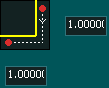
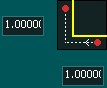
Outside Corner probing
- When Outside corner probing is selected a set of 2 distance boxes are displayed on the screen at each corner.
- These boxes represent how far the X and Y axis will travel around the corner before starting the 2nd probe.
- The Red dot indicates the position of the probe at the start of the probing cycle and the Yellow line represents the object being probed.
- The White arrow represents the order in which probing will occur in the cycle and also the direction of travel the probe will take
- Each probing cycle is an automatic two part probing cycle.
- The probing will occur at the speed entered in the Probing Feedrate box
- After touching off the Axis will return to the start position at rapid speed.
- Enter the Probe diameter into the Probe Diameter box
The probe will start moving in the +X direction at the specified Probing feed rate until it touches the part.
The Probe will return to its start position.
The probe will move at probing speed in the +Y direction for the distance shown.
The probe will move at probing speed in the +X direction for the distance shown.
The probe will start moving in the -Y direction at the specified Probing feed rate until it touches the part.
The Probe will return to the start of the 2nd probing and display its new coordinates based on its relative position to the probed surfaces.
The probe will start moving in the -Y direction at the specified Probing feed rate until it touches the part.
The Probe will return to its start position.
The probe will move at probing speed in the +X direction for the distance shown.
The probe will move at probing speed in the -Y direction for the distance shown.
The probe will start moving in the -X direction at the specified Probing feed rate until it touches the part.
The Probe will return to the start of the 2nd probing and display its new coordinates based on its relative position to the probed surfaces.
The probe will start moving in the -X direction at the specified Probing feed rate until it touches the part.
The Probe will return to its start position.
The probe will move at probing speed in the -Y direction for the distance shown.
The probe will move at probing speed in the -X direction for the distance shown.
The probe will start moving in the +Y direction at the specified Probing feed rate until it touches the part.
The Probe will return to the start of the 2nd probing and display its new coordinates based on its relative position to the probed surfaces.
The probe will start moving in the +Y direction at the specified Probing feed rate until it touches the part.
The Probe will return to its start position.
The probe will move at probing speed in the -X direction for the distance shown.
The probe will move at probing speed in the +Y direction for the distance shown.
The probe will start moving in the +X direction at the specified Probing feed rate until it touches the part.
The Probe will return to the start of the 2nd probing and display its new coordinates based on its relative position to the probed surfaces.
INFORMATION: If you select the wrong probing cycle by mistake, Press Feed hold or ESC on the keyboard. This will bring probing to a halt and you can select the correct one.
CAUTION: It is advisable to quickly test your touch probe before starting a probing cycle to ensure it is working properly. This is done by triggering the Probe and observing the  indication at the top of the screen. When triggered the indication will change green
  This is done by touching the probe tip in case of a 3D touch probe or by tapping the plate against the tool in case of a probing plate.


 Spanish
  French
  German
  Simplified Chinese