

 Spanish
  French
  German
  Simplified Chinese
 G41- Cutter Compensation Left
This feature is for MASSO G3 & MASSO Touch only and is currently undergoing Beta testing in version 5.100b available for download in MY WORKSHOP
The cutter will move to the left side of the original tool path by the amount specified by the compensation parameters.
The compensation parameters are made up of 3 values which work together to specify the offset value.
The tool path offset is calculated as follows:
Toolpath Offset = (Tool Diameter + Wear Diameter) / 2 + P Value
Tool diameter - This is the nominal diameter of the cutter eg 10mm and is located in the F4 screen Tool table. If tool compensation is done in CAM then this can be left as 0
Wear diameter - This is the wear adjustment of the cutter over or undersized and is located in the F4 screen Tool table.
P value - This is the radius to offset the tool path by and is typically used in hand coded Gcode.
For a more detailed explanation of managing tools in the F4 tool table please see the section managing Tool Diameter and Wear values at the bottom of the page.
Syntax & Parameters
- G41 - MASSO uses the Diameter and Wear values specified for the current tool
- P value - This is the radius to offset the toolpath by and is added to the Wear diameter offset. If no P Value is specified it will use the Wear Diameter in the F4 tool table.
- Tool diameter - This is the diameter of the cutter and is a positive value.
- Wear Diameter - This is how much wear there is on the tool diameter. This value is entered as a negative number for an undersized tool while a positive value can be used for an oversized tool.
Example Program
N10 T1 M06
N20 G41
N10 T1 M06
N20 G41 P5
N10 T1 M06
N20 G00 X-50 Y-25 Z25
N30 G01 Z-5 F250
N40 G41
N50 X-25 (lead in)
N60 X100
N70 Y-100
N80 X25
N90 Y25
N100 G40
N110 X25 Y50 (Lead out)
N120 G00 Z25

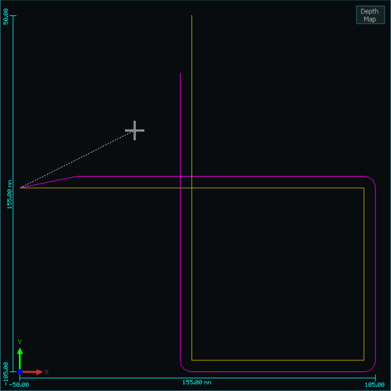

Compensated Toolpath shown in RED
Note: The final move is not shown in the compensated tool path after the cutter Compensation is turned off.
Troubleshooting
If your compensated toolpath shows loops as shown in the example below it means that the compensated cutter size is too large for the purpose and is causing toolpath lines to cross one another.
Select a smaller cutter more suited to the job.


Cutter too large Cutter size correct
WARNING: The following Cutter Compensation rules are important and not adhering to them may cause unpredictable results, damage to the part being machined or to the machine itself.
Cutter Compensation Rules
- Cutter compensation paths are calculated and displayed when the Gcode file is loaded.
- Outside corners are automatically radiused.
- Valid in the G17 XY Plane only
- Only valid for X & Y axis moves.
- Do not include Z, A or B axis moves in the compensated section of your Gcode file as this may cause unpredictable results.
- Move to the required cutting height before turning on cutter compensation.
- Do not include non cutting moves in the compensated section of your Gcode file as this may cause unpredictable results. eg Turning coolant on or off.
- A lead in move is required to a safe location at the start of compensation.
- A lead out is required to a safe location at the end of the compensation.
- The lead out move is not shown on screen as a compensated move.
- Use linear moves for both Lead in and lead out.
- The lead in and out distance must be greater than the cutter radius.
- Specify both the X & Y coordinates on the first move after leaving Cutter compensation or you may experience an unpredictable move.
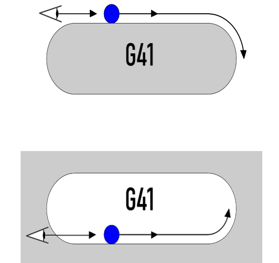
The best way to think of G41 is that you are standing behind the cutter as it moves away from you.
The cutter will move to the Left side of the original tool path
Managing Tool Diameter, Wear Diameter and P Value
MASSO cutter compensation has been designed for maximum flexibility and compatibility.
There are several different ways that users can manage their tools in the tool table depending on what works best for them and what what they may already be used to.
The Tool Diameter and Wear Diameter values specified for the current tool is automatically applied whenever G41 is turned on
Tool Offset Calculation
The Compensation value used to off set the cutter is made up of 3 parameters.
Tool Diameter, Wear Diameter and P Value
The tool path offset is calculated as follows:
Toolpath Offset = (Tool Diameter + Wear Diameter) / 2 + P Value
P Value
The P value is used to specify a cutter offset in Gcode and is the radius to offset the tool path by. eg a 10mm cutter would use a P Value of 5mm
It is typically used in hand coded Gcode where you can hand code a simple toolpath and want to offset the cutter to account for the tool radius instead of having to take it into account in the Gcode itself.
It is a lot easier to hand code a 100mm square without taking the cutter into account and then use a P value to offset the cutter than to work out the coordinates for a particular tool.
This would be used on a machine where the Tool Diameter is set to 0 in the F4 tool table which would be typical where Tool offset is calculated in CAM or you do not use Cutter compensation.
If you have a Wear diameter assigned to the tool then this will be taken into account when the offset is calculated.
It would not be common for the P Value to be used with the Tool Diameter but you may have an application where you wish to use it.
Tool Diameter
How the Tool Diameter value is used will depend on your Gcode.
If the Tool Path offset is managed in your CAM software then the Tool Diameter will be left a 0. This would be the most common situation when using CAM software.
If the Tool Path does not already have the Tool offset included within the Gcode such as a hand coded Gcode file, then the Tool Diameter value can be used to offset the tool.
This is the same as using the P Value except the offset is stored in the F4 tool table instead of the being in the Gcode itself.
The Tool Diameter value can be the actual diameter of the cutter taking into account the amount of wear the cutter may have.
Alternatively it can be the nominal diameter of the cutter and final adjustment of the cutter size can be done using the Wear diameter value.
Wear Diameter
The Wear Diameter is used to adjust the tool diameter as a tool wears through use.
The Wear Diameter can be used and without the Tool Diameter or a P Value
It can also be used to indicate a tool is oversized.
- A negative wear value means a tool is undersized.
- A positive wear value means a tool is oversized
Example
A 10mm tool with a -0.5mm wear indicates that the tool is undersized and is 9.5mm in diameter.
10 + (-0.5) = 9.5mm tool
A 10mm tool with a 0.5mm wear indicates that the tool is oversized and is 10.5mm in diameter.
10 + (0.5) = 10.5mm tool