


 Spanish
  French
  German
  Simplified Chinese
 VFD and Spindle Testing
Introduction
This guide outlines the steps needed to troubleshoot a VFD / Spindle problem.
The video at the bottom of this page will take you through the test procedure step by step and you can follow the written instructions below.
It's purpose of the troubleshooting guide is to identify if the problem is located within MASSO or the VFD.
If the problem is identified as the VFD or Spindle please contact your supplier for further troubleshooting procedures.
A Spindle need to know two things to work, how fast and what direction.
- How fast is determined by the voltage on Pin 1 of the MASSO Spindle control
- The direction is determined by the Clockwise / Counter Clockwise outputs on pins 4 & 5, 6 & 7 of Spindle control.
Test Equipment
- Multimeter
Testing the Speed control
Enter a spindle speed of 50% of your spindles maximum speed into the spindle speed box on the F2 screen and press the Spindle CW button.
In this example the maximum spindle speed is 24000 so 12000 is used for the test.
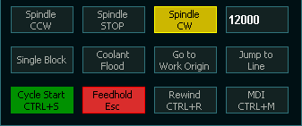
Measure the voltage between Spindle control Pin 1 and one of the Black terminals on MASSO.
You should see a reading of 5 volts. (Note: it will now show exactly 5 volts but it will be close)
If you are seeing 5 volts the spindle speed control it working ok and you can proceed to testing the direction signal.
If the voltage is low then unplug the Spindle control plug from MASSO and test again.
If the voltage is now correct then you have a problem with the VFD or its wiring as something is dragging the voltage down.
Check your wiring and consult your VFD supplier for further assistance.
If the Voltage is still low, check the spindle settings.
Make sure you have VFD selected and the spindle speed at 10 volts setting, is double your test speed.
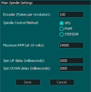
If you still cannot get 5 volts you may have a damaged spindle control output.
Please contact MASSO support with a description of the problem and a screen print of the F2 screen showing the Speed control test in progress.
Testing Direction Clockwise
Step 1
Stop the spindle with the Spindle Stop button and measure the voltage across Spindle control Pins 4 & 5.
Put the Black meter lead on Pin 4 and the Red meter lead on Pin 5.
You should read a voltage coming from the VFD. This voltage varies depending on the VFD but 24 volts is common.
If the voltage reading is negative then you have pins 4 & 5 reversed, correct and test again.
If the voltage reading is correct move to Step 2
If you do not see a voltage or it is lower than expected you may have a faulty VFD or faulty wiring or optocouple
Check the F2 screen to ensure that Spindle Stop is lit up yellow to indicate the spindle is turned off. 
Check that optocouple by unplugging the Spindle control plug and testing the voltage across pins 4 & 5 on the plug.
If the voltage remains low then the problem is the VFD or the cable. Check your cabling and consult your VFD supplier for further assistance,
If it now shows the correct voltage then you have a problem with the optocouple.
How to replace a faulty Optocouples on MASSO G3 & MASSO Touch
How to replace a faulty Optocouples on MASSO G2
If after replacing the Optocoupler it continues to drop the voltage when you connect the VFD please contact MASSO support for further troubleshooting.
Step 2
If the voltage is correct, Enter a spindle speed of 50% of the maximum spindle speed and press the Spindle CW button.
Measure the voltage across Spindle control Pins 4 & 5 and this time it should read less than 0.3 volts.
If the voltage shows 0.3v or less, the clockwise signal is correct and the problem is with the VFD. Please consult your VFD supplier for further assistance.
If the voltage drops when the Spindle is set to CCW but does not get as low as 0.3v, this may indicate a wiring issue between MASSO and the VFD or a faulty optocouple.
For example a drops from 24v to 5v
Please check the wiring between MASSO and the VFD to ensure that you do not have a high resistance connection.
If the voltage does not then the Optocouple in MASSO is faulty and needs replacing.
How to replace a faulty Optocouples on MASSO G3 & MASSO Touch
How to replace a faulty Optocouples on MASSO G2
Testing Direction Counter Clockwise
Step 1
Stop the spindle with the Spindle Stop button and measure the voltage across Spindle control Pins 6 & 7.
Put the Black meter lead on Pin 6 and the Red meter lead on Pin 7.
You should read a voltage coming from the VFD. This voltage varies depending on the VFD but 24 volts is common.
If the voltage reading is negative then you have pins 6 & 7 reversed, correct and test again.
If the voltage reading is correct move to Step 2
If you do not see a voltage or it is lower than expected you may have a faulty VFD or faulty wiring or optocouple
Check the F2 screen to ensure that Spindle Stop is lit up yellow to indicate the spindle is turned off.
Check that optocouple by unplugging the Spindle control plug and testing the voltage across pins 6 & 7 on the plug.
If the voltage remains low then the problem is the VFD or the cable. Check your cabling and consult your VFD supplier for further assistance,
If it now shows the correct voltage then you have a problem with the optocouple.
How to replace a faulty Optocouples on MASSO G3 & MASSO Touch
How to replace a faulty Optocouples on MASSO G2
If after replacing the Optocouple it continues to drop the voltage when you connect the VFD please contact MASSO support for further troubleshooting.
Step 2
If the voltage is correct, Enter a spindle speed of 50% of the maximum spindle speed and press the Spindle CCW button.
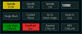
Measure the voltage across Spindle control Pins 6 & 7 and this time it should read less than 0.3 volts.
If the voltage shows 0.3v or less, the clockwise signal is correct and the problem is with the VFD. Please consult your VFD supplier for further assistance.
If the voltage drops when the Spindle is set to CCW but does not get as low as 0.3v, this may indicate a wiring issue between MASSO and the VFD or a faulty optocouple.
For example a drops from 24v to 5v
Please check the wiring between MASSO and the VFD to ensure that you do not have a high resistance connection.
If the voltage does not change then the Optocouple in MASSO is faulty and needs replacing.
How to replace a faulty Optocouples on MASSO G3 & MASSO Touch
How to replace a faulty Optocouples on MASSO G2

