Spanish
  French
  German
  Simplified Chinese
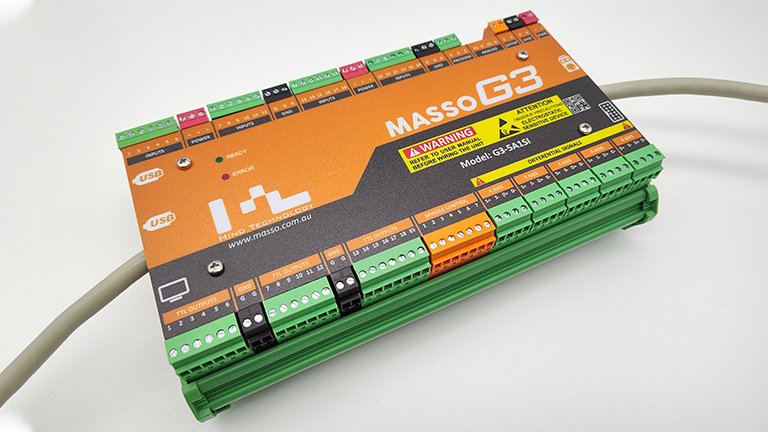
 MASSO G3 Touch Wiring Module
IMPORTANT: The MASSO G3 Touch wiring module does not provide extension for the two ananlog inputs on the MASSO G3 Touch.
Description
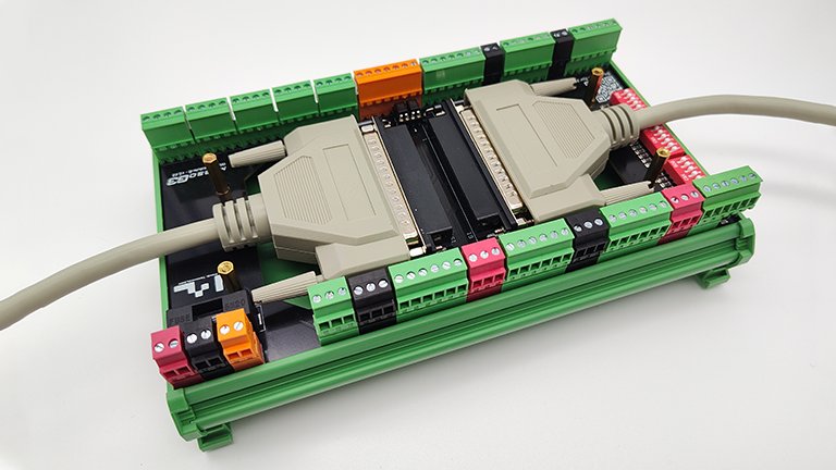
The MASSO G3 Touch wiring module is an extension module used to extend the inputs and outputs from inside the MASSO G3 Touch cabinet to a machine location (This would normally be on the machine itself).
By using this module, the cable management between the MASSO G3 Touch and the machine becomes very simple and if the cables are damaged then they can be replaced quickly.
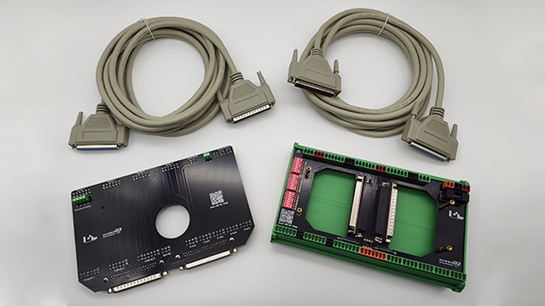
The extension kit comes with the following items:
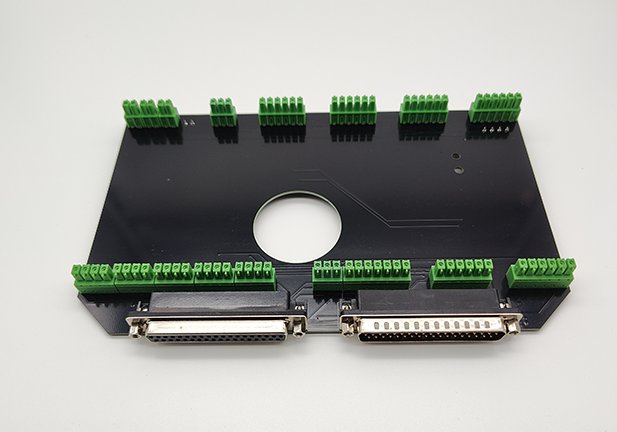
- Local extension module board that plugs into MASSO Touch.
- D cables to connect the two boards.
- Machine side extension Module used to wire your machine inputs and outputs.
Features of the MASSO G3 Touch Wiring module include
- A fuse holder for the 1 amp fuse to power your MASSO G3 Touch.
- Power is provided at the Machine side extension board and is sent to the MASSO G3 Touch through the extension cables.
- 24 Dip switches which can be used to switch enable pull-up resistors for inputs if needed.
- Optical isolation for the Spindle CW and CCW outputs on the Machine side.
- A DIN rail mount for the Machine side module of the Wiring module.
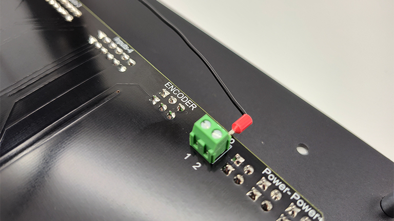
- The Local extension board has connectors for inputs 1, 2, and Estop. This will allow the existing buttons and the Estop button on the front of the MASSO Touch to be reconnected.
- The Local extension board has an access port for the onboard battery.
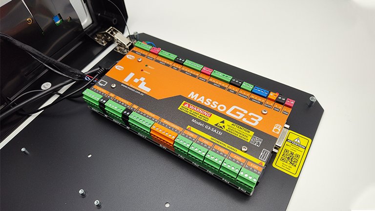
Installing your MASSO G3 Touch Wiring Module
Step 1
Open your MASSO G3 Touch cabinet
Step 2
- Remove the top label from your MASSO and set it aside along with the 4 screws that secure it in place.
- Remove the wires from inputs 1, 2, POWER and Estop 2 as these will need to be connected to the Local module.
- Remove all connectors from your MASSO G3 Touch and set them aside as you will require these later.
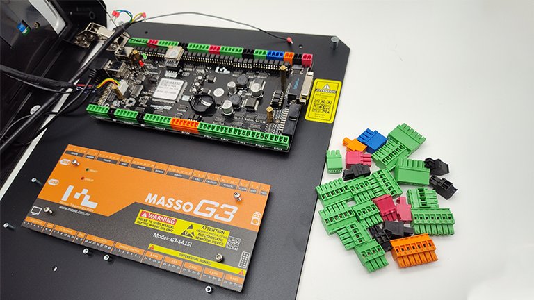
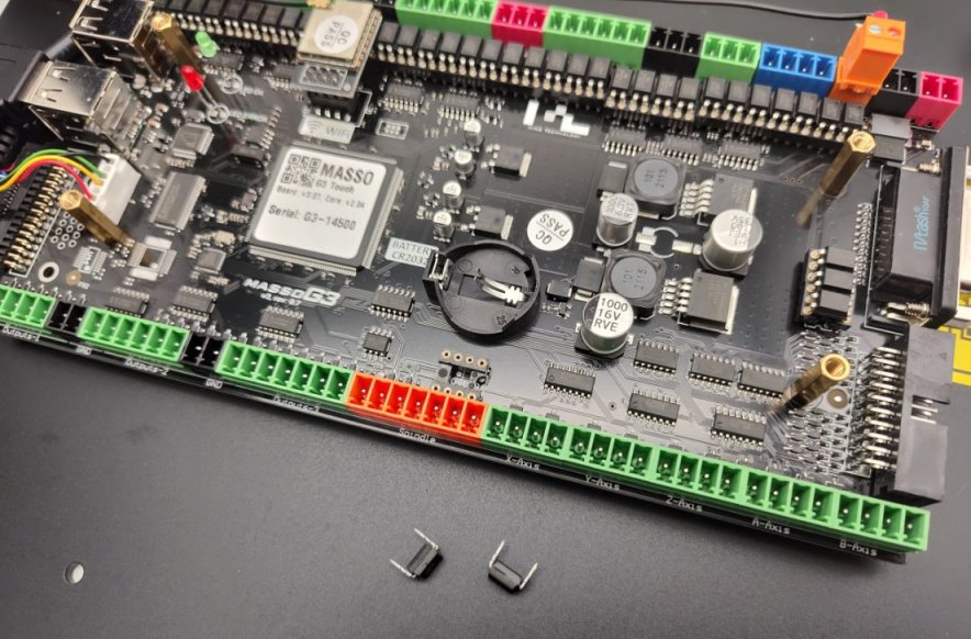
Carefully remove the 2 spindle optocouple IC's from the MASSO board.
INFORMATION: If you have not yet installed your backup battery this would be a good time to do it though you can do it later if you like.
Step 3
Step 4
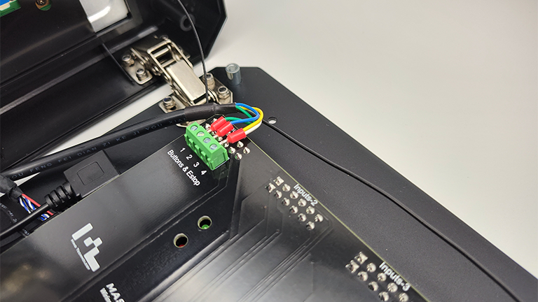
- Connect the Black Estop wire to Estop 1 or Estop 2 on the Local extension board.
- If you have a pendant installed on MASSO connect to Estop 1.
- If you do not have a pendant installed on MASSO connect to Estop 2.
Step 5
- Pass the two 37-pin connector cables through the slotted access hole in MASSO.
- Note that when you pass the cables through the rear of the MASSO cabinet you want one male and one female connector.
- Plug them into the Local extension board and secure them in place using the thumbscrews on the cable plugs.
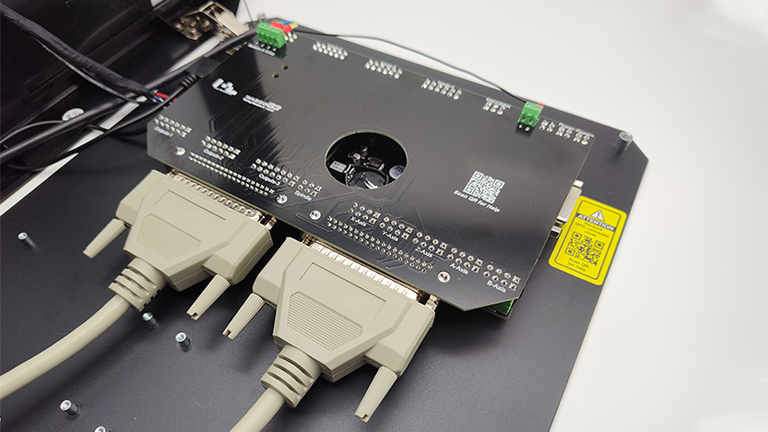
The MASSO Touch end is now completed and the cabinet can be closed.
Machine Side
Step 1
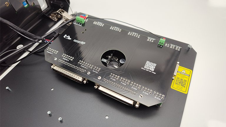
Install the two optocouplers IC's that you removed for your MASSO touch and install them into the machine side module.
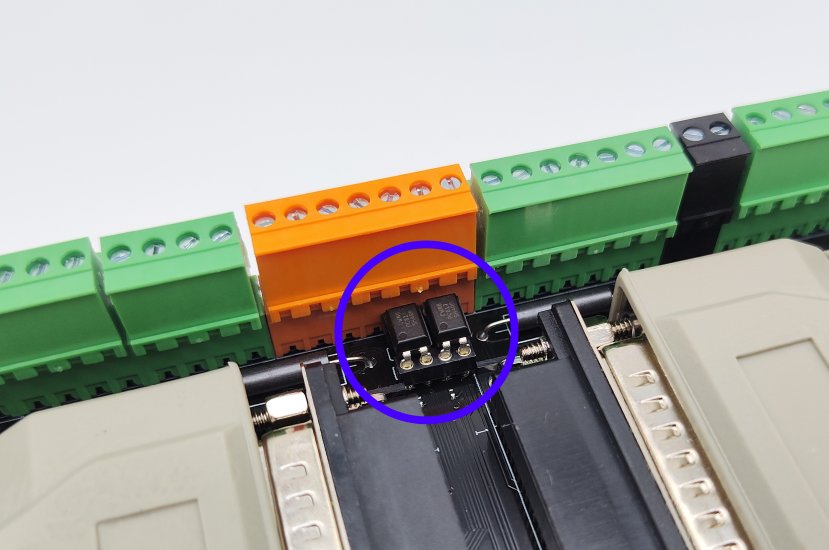
WARNING: Note the little dot beside pin1 on the IC and ensure that it is orientated the same as in the photo below.
Step 2
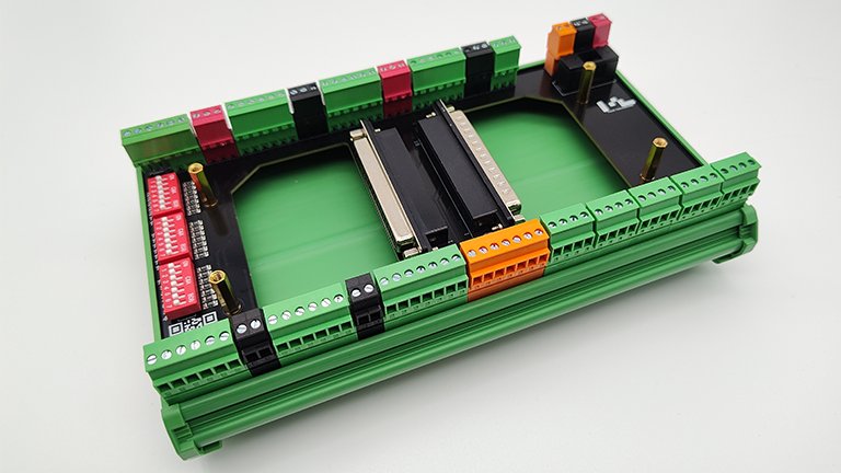
Install the screw terminal plugs you removed from your MASSO G3 Touch into the machine side extension board as shown below.
Step 3
- Connect the two 37-pin cables to the machine side module.
- One connector is male and the other is female so the cable connections will only connect to the right connector.
- Secure them in place using the thumb screws on the cable plugs.
Step 4
Secure the MASSO G3 cover from your MASSO G3 Touch to the board using the 4 screws.