Spanish
  French
  German
  Simplified Chinese
 Axis Testing
INFORMATION: This Test feature is for the MASSO G3 and MASSO Touch. It available in the Beta version 5.100b and can be downloaded from MY WORKSHOP, see the note in the Introduction section for more information.
Introduction
This guide outlines the procedure for troubleshooting an axis that is not working to determine if the axis output has been damaged.
It shows how to test the Step and Direction outputs of an axis using the built in STEP and DIRECTION test function.
Please Note: This feature is only available in the Beta test version 5.100b which can be downloaded from MY WORSKOP.
Backup all settings before loading this software as you will need them to return to your original software version after testing is complete
After you load v5.100b you will be able to use the test feature on the X Y & Z axis to do the testing using the step by step instructions below.
Once you are finished reload your original software version and load back the settings file you saved.
Do not continue with v5.100b for setting up or running your machine.
Test Equipment
- Multi-meter
Testing Method
Pressing the  button will toggle the Step output from High to Low or from Low to High
Pressing the  button will toggle the Direction output from High to Low or from Low to High
Testing Axis Step Differential Output
- Disconnect all wires from the step and direction of the axis you want to test. This can be done by removing the Axis connector.
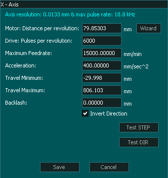
- Open the page of the Axis you want to test in the F1 Screen
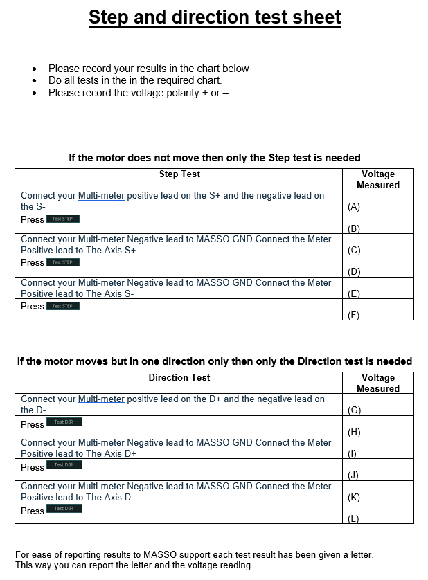
- Connect your Multi-meter to the S+ & S- of the axis under test. Put the Multi-meter positive lead on the S+ and the negative lead on the S-.
- Read the voltage and you should see 4 volts
- Note the polarity of the measured voltage.
- Press the button.
- Read the voltage and you should see between 4 volts
- The polarity of the measured voltage should be now be reversed to the original reading.
Each time you press the button the voltage reading of 4 volts should remain but polarity will reverse.
This is a good test and the differential output is working correctly.
If the differential output is not working correctly please follow the instructions below for the Common Ground Output test.
This will determine the extent of the axis damage.
Testing Axis Step Common Ground Output
- Disconnect all wires from the step and direction of the axis you want to test. This can be done by removing the Axis connector.
- Open the page of the Axis you want to test in the F1 Screen
- Connect your Multi-meter Negative lead to MASSO GND
- Connect the Meter Positive lead to The Axis S+ and you will see either 4 volts or 0 volts.
- Press the button.
- If you saw 4 Volts on the S+ you will now see 0v
Each time you press the button the voltage will toggle between 0 and 4 volts This is a good test result.
If you do not see the voltage toggle between 0 & 4 volts each time you press the button you have a damaged S+ output, continue to test S-
- Connect the Meter Positive lead to The Axis S- and you will see either 4 volts or 0 volts.
- Press the button.
- If you saw 4 Volts on the S- you will now see 0v
Each time you press the button the voltage will toggle between 0 and 4 volts This is a good test result.
If you do not see the voltage toggle between 0 & 4 volts each time you press the button you have a damaged S- output
Testing Axis Direction Differential Output
- Disconnect all wires from the step and direction of the axis you want to test. This can be done by removing the Axis connector.
- Open the page of the Axis you want to test in the F1 Screen
- Connect your Multi-meter to the D+ & D- of the axis under test. Put the Multi-meter positive lead on the D+ and the negative lead on the D-.
- Read the voltage and you should see 4 volts
- Note the polarity of the measured voltage.
- Press the button.
- Read the voltage and you should see between 4 volts
- The polarity of the measured voltage should be now be reversed to the original reading.
Each time you press the button the voltage reading of 4 volts should remain but polarity will reverse.
This is a good test and the differential output is working correctly.
If the differential output is not working correctly please follow the instructions below for the Common Ground Output testing
This will determine the extent of the axis damage.
Testing Axis Direction Common Ground Output
- Disconnect all wires from the step and direction of the axis you want to test. This can be done by removing the Axis connector.
- Open the page of the Axis you want to test in the F1 Screen
- Connect your Multi-meter Negative lead to MASSO GND
- Connect the Meter Positive lead to The Axis D+ and you will see either 4 volts or 0 volts.
- Press the button.
- If you saw 4 Volts on the D+ you will now see 0v
Each time you press the button the voltage will toggle between 0 and 4 volts. This is a good test result. Repeat for the D-
If you do not see the voltage toggle between 0 & 4 volts each time you press the button you have a damaged D+ output, continue to test D-
- Connect the Meter Positive lead to The Axis D- and you will see either 4 volts or 0 volts.
- Press the button.
- If you saw 4 Volts on the D- you will now see 0v
Each time you press the button the voltage will toggle between 0 and 4 volts This is a good test result.
If you do not see the voltage toggle between 0 & 4 volts each time you press the button you have a damaged D- output
Interpreting Test Results
If the Step differential test does not show 4 volts and the polarity reversing between S+ & S- when the button is pressed you have a faulty Step output.
If the Direction differential test does not show 4 volts and the polarity reversing between D+ & D- when the button is pressed you have a faulty Direction output.
Important!