Spanish
  French
  German
  Simplified Chinese
 Popup Tool changer- Beta
This tool changer is for MASSO G3 and MASSO Touch and is only available in Beta version 5.100b or higher.
These tool changer types are common on Multicam machines
Selecting the tool changer
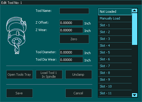
In the Tool Changer window select Pop Up Tool Changer and double click for settings.
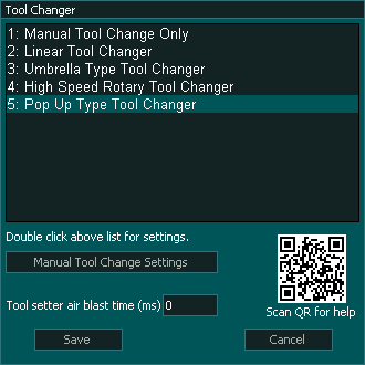
 This timer determines the duration in Milliseconds of the Air blast used to clean the tool setter before the tool is measured after a tool change.
Assign an output for the Tool setter Air Blast 
Pop Up Tool Changer Settings
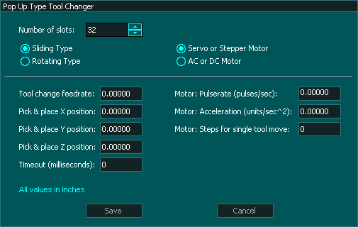
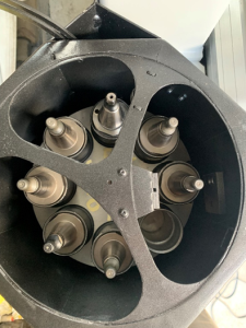
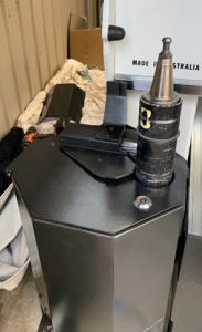
This tool change logic supports rotary popup (image 1 & 2) or sliding popup (image 3) tool changers with up to 32 tools.
The drive motor for the tool changer can be either an AC, DC, stepper or servo motor.
All popup tool changer use a home position sensor.
This Tool changer homes when you home your machine.
Tool changer Parameters
The tool changer window is broken into 3 sections.
Depending on what type of tool changer you have various options displayed will change.
The following 5 options are common to all tool changers though not all are needed.

 Number of Slots: - All Tool changers can can be set from 4 slots up to 32 tool slots.
 Select this option of you have sliding popup tool changer. (image 3)
 Select this option of you have rotary popup tool changer. (image 1 & 2)
 Select this option if you are using a stepper or servo motor to move the tool cups
 Select this option if you are using an AC or DC motor to move the tool cups
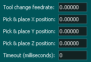
 This is the speed at which the Tool is picked up or dropped off.
 This is the X axis machine coordinate where the tool will popup.
 This is the Y axis machine coordinate where the tool will popup.
 This is the Z axis machine coordinate that the z axis moves too to drop off and pick up a new tool.
 This setting is in milliseconds and defines how long the tool changer has to perform the Homing of the Tool changer before a Homing alarm is displayed.
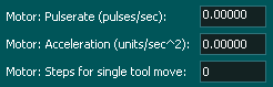
The following options are only available when Servo or Stepper motor is selected otherwise it is removed as an option.
 Enter the number of pulses per second. This determines the maximum feed rate that the tool cups can move.
 Enter your motor acceleration
 Enter the number of steps required to move to the next tool.
Inputs and Outputs
If there are inputs and outputs that your machine does not have or does not use then do not assign them and the MASSO Tool change logic will ignore them and move to the next task in the tool change logic sequence.
Syntax used in this document for Tool Changer inputs and outputs
"Tool Changer - Output 1" means Tool Change - 1 and it is an output
"Tool Changer - Input 1" means Tool Changer -1 and it is an Input
Note: Any tool changer input or output can be assigned to any Input or Output on MASSO. The tool changer number does not refer to an actual input or output port.
INPUTS
Tool Changer - Input 1 - Tool in spindle Status, HIGH means tool in spindle.
Tool Changer - Input 2 - Tool in tool loader cup, HIGH means in cup.
Tool Changer - Input 3 - tool tray home position detect.
Tool Changer - Input 4 - Pulse/Strobe signal for each tool position.
Tool Changer - Input 5 - Tool Door OPEN signal.
Tool Changer - Input 6 - Tool Door CLOSE signal. (INFORMATION: If only one sensor for Tool Door Open/Close status is used then do not assign this function to any input.)
Tool Changer - Input 7 - Tool Loader UP signal.
OUTPUTS
Tool Changer - Output 1 - STEPS for Stepper or CW signal for AC or DC motor.
Tool Changer - Output 2 - DIRECTION for Stepper or CCW signal for AC or DC motor.
Tool Changer - Output 3 - Tool Door OPEN signal.
Tool Changer - Output 4 - Tool Door CLOSE signal. (INFORMATION: If only one valve is used for the Tool Door open/close then do not assign this function to any output)
Tool Changer - Output 5 - Tool Loader UP signal.
Tool Changer - Output 6 - Tool Loader DOWN signal. (INFORMATION: If only one valve is used for Tool Loader UP/DOWN then do not assign this function to any output)
Tool Changer logic
During machine homing:
- After all the axis of the machine has been homed as per the homing sequence the tool changer logic will home the tool changer.
- The tools will be retracted and the system will wait as per the timeout period set up in the Tool Changer Settings.
- Once retraced the tools will move until the tool tray home position detect is not activated.
- Then the system will automatically rotate the tool to the last loaded position (empty tool slot).
- IMPORTANT: The home position of the tool changer must be marked as Slot "1".
Tool Door logic - Type 1
This logic uses a single output to move the Tray up and down
Door Open
- "Tool Changer - Output 3" goes HIGH to open the Tool door, then the system waits for 6 seconds for the "Tool Changer - Input 5" (Tools Door Open) signal to go HIGH, else gives an error.
Door Close
- "Tool Changer - Output 3" goes Low to close the Tool door, then the system waits for 6 seconds for the "Tool Changer - Input 5" (Tools Door Open) signal to go Low, else gives an error.
Tool Door logic - Type 2
This logic uses a dual outputs to move the tray up and down
Door Open
- "Tool Changer - Output 3" goes HIGH to open the Tool door, then the system waits for 6 seconds for the "Tool Changer - Input 5" (Tools Door Open) signal to go HIGH, else gives an error.
- "Tool Changer - Output 3" goes LOW.
Door Close
- "Tool Changer - Output 4" goes High to close the Tool door, then the system waits for 6 seconds for the "Tool Changer - Input 6" (Tools Door Closed) signal to go High, else gives an error.
- "Tool Changer - Output 4" goes LOW.
Tool Change
When a tool change command is received, the tool changer logic works in the followings steps:
- Spindle is turned OFF and the system waits for the spindle to stop as per the spindle "Spin down delay" value in the spindle settings.
- The system checks if the current tool in the spindle is setup in a slot is the F4-Tools screen, else gives an error.
- The system checks if the tool to load is setup in a slot is the F4-Tools screen, else gives an error.
- Z-axis moves up to the homing position.
- X & Y-axis moves to "Pick and Place Position"
- The Tool Door Opens
- Tool Changer - Output 5 - goes High to move the Tool cup up and waits for "Tool Changer input - 7" to go High (Tool Loader UP signal) else gives an error
- Z-axis moves down to the Tool Pick & Place Z position
- "Chuck Clamp M10/M11" goes HIGH to unclamp the tool, then the system waits for 6 seconds for the "Tool Changer - Input 1" (Spindle draw bar Status) signal to go HIGH, else gives an error.
- "Tool Changer - Input 2" - goes HIGH to indicate tool in cup else gives an error
- Z-axis Moves Up to Tool holder Z clearance height
- "Tool Changer Outputs 1& 2" are used to move the tools to the next tool position using Tool Changer Input-2 to count the position pulses
- Once the desired tool is in position the "Tool Changer - Output 1 &2 " stop tool tray rotation.
- Z-axis moves DOWN to the Tool Pick & Place Z position.
- "Chuck Clamp M10/M11" goes LOW to clamp the tool, then the system waits for 6 seconds for the "Tool Changer - Input 1" (Spindle draw bar Status) signal to go LOW, else gives an error.
- Tool Changer - input 1, (Tool in Place status), to go HIGH, else gives "Tool Error" alarm and displays "Tool in spindle not detected"
- Z-axis moves Home Position
- "Tool Changer - Output 6" goes Low to retract the tool loader cup
- The Tool door closes
Dust Hood
Assigning Tool slots