

 Spanish
  French
  German
  Simplified Chinese
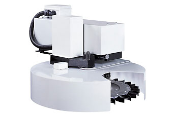
 Umbrella Tool Changer
WARNING: The below instructions are for MASSO G3 controllers running software v5.0 and above. For any other software version, the below instructions CAN NOT be used, please contact support if you have any other software version with umbrella tool changer.
Selecting the tool changer
In the Tool Changer window select the tool changer and double click for settings.
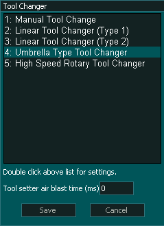
INFORMATION: The Tool setter air blast is used to clean dust from the tool setter after the tool has been changed and before the tool is measured. It is not used during the tool change process.
Setting up the tool changer as per your machine
There are different types of umbrella tool changer setups depending on the tool changer design. In most cases, an external arm moves the tools into position for tool unloading and loading, but in some designs, the machine's axis is used to position the spindle above the tool change position.
MASSO umbrella tool changer logic provides options to easily set up tool changer logic as per your machine requirements.
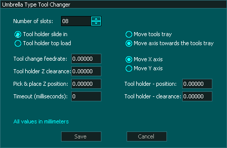
Settings 1 - Tool holder sliding or top-loading type
Settings 2 - Tool holder moving under spindle or spindle moved using axis
"Move axis" option
Timeout (milliseconds)
Tool Changer Inputs and Outputs
Syntax used in this document for Tool Changer inputs and outputs
"Tool Changer - Output 1" means Tool Change - 1 and it is an output
"Tool Changer - Input 1" means Tool Changer -1 and it is an Input
Note: Any tool changer input or output can be assigned to any Input or Output on MASSO. The tool changer number does not refer to an actual input or output port.
WARNING: The below input and output pins are for MASSO G3 controllers running software v4.02 and above. For any other software version, the below instructions CAN NOT be used, please contact support if you have any other software version with umbrella tool changer.
INFORMATION: If your machine does not have a sensor for one or more of the inputs below then do not assign an input to that function and the tool change logic will ignore the input and will continue.
INPUTS
- Tool Changer – Input 1 for Homing Sensor (to be used to find Slot-1 position when the machine is homed)
- Tool Changer – Input 2 for Pulse Counter Sensor (this pulse signal is required as each tool passes the sensor)
- Tool Changer – Input 3 for Dust Hood UP OK signal (High means hood UP)
- Tool Changer – Input 4 for Tools Retract OK (signal from sensor or switch telling the system that the tools are retracted away from the spindle)
- Tool Changer – Input 5 for Tools In Position OK (signal from a sensor or switch telling the system that the tools fully extended and at loading position)
- Tool Changer – Input 6 for Spindle in INDEX position (signal from VFD, telling the system that the spindle is Indexed and locked in position)
- Tool Changer – Input 7 for Drawbar Locked (signal from sensor or switch telling the system that drawbar is in the locked position)
- Tool Changer – Input 8 for Drawbar Unlocked (signal from sensor or switch telling the system that drawbar is in unlocked position)
OUTPUTS
- Chuck Clamp M10/M11 for spindle drawbar clamp and un-clamp (Low to clamp and High to un-clamp)
- Tool Changer – Output 1 to move Dust Hood UP/DOWN (When HIGH the hood will move UP)
- Tool Changer – Output 2 to Rotate Tools Tray
- Tool Changer – Output 3 when LOW will Retract Tools (away from spindle) and when HIGH will Bring Tools In Position (for tool change)
- Tool Changer – Output 4 when HIGH will give a signal to VFD to Start JOGGING the spindle at very low RPM.
- Tool Changer – Output 5 when HIGH will give a signal to VFD to Automatically stop and lock in INDEX position.
- Tool Changer – Output 6 for spindle clean air blast
Tool Changer logic
During machine homing:
- After all the axis of the machine has been homed as per the homing sequence the tool changer logic will home the tool changer.
- The tools will be retracted and the system will wait as per the timeout period set up in the Umbrella Tool Changer Settings.
- Once retraced the tools will rotate until the homing sensor on the tools is not activated.
- Then the system will automatically rotate the tool to the last loaded position (empty tool slot).
- IMPORTANT: The home position of the tool changer must be marked as Slot "1".
When a tool change command is received, the tool changer logic works in the followings steps:
- The spindle is turned OFF and the system waits for the spindle to stop as per the spindle "Spin down delay" value in the spindle settings.
- The system checks if the current tool in the spindle is set up in a slot is the F4-Tools screen, else gives an error.
- The system checks if the tool to load is set up in a slot is the F4-Tools screen, else gives an error.
- Z-Axis moves UP to the Tool Pick & Place Z position.
- If spindle indexing is required and "Tool Changer - Input 6 (Spindle in INDEX position)" is assigned to one of the MASSO inputs then:
- Tool Changer - Output 4 goes HIGH for VFD to Start JOGGING the spindle at a very low RPM.
- Tool Changer - Output 5 goes HIGH for VFD to Automatically stop and lock in INDEX position.
- The system waits for the "Tool Changer - Input 6 (Spindle in INDEX position)" to go HIGH.
- "Tool Changer - Output 3" goes HIGH to move Tools In Position to unload the current tool. The system waits for time setup in Timeout settings for the "Tool Changer - Input 5" (Tools In Position) signal to go HIGH, else gives an error.
- "Chuck Clamp M10/M11" goes HIGH to unclamp the tool.
- If spindle "Drawbar Locked & Unlocked" signals are assigned to any of the MASSO inputs then:
- The system waits for the "Tool Changer - Input 7 (Drawbar Locked)" to go LOW.
- And waits for the "Tool Changer - Input 8 (Drawbar unlocked)" to go HIGH.
- Z-Axis moves up to the Tool holder Z clearance position.
- "Tool Changer - Output 2" goes HIGH to Rotate Tools and counts pulses from "Tool Changer - Input 2".
- Once the desired tool is in position the "Tool Changer - Output 2" goes LOW to stop tool tray rotation.
- Z-Axis moves DOWN to the Tool Pick & Place Z position.
- Tool Changer - Output 6 (spindle clean air blast) goes HIGH as the Z axis descends.
- Tool Changer - Output 6 (spindle clean air blast) goes Low when Z axis is in position.
- "Chuck Clamp M10/M11" goes LOW to clamp the tool.
- If spindle "Drawbar Locked & Unlocked" signals are assigned to any of the MASSO inputs then:
- The system waits for the "Tool Changer - Input 7 (Drawbar Locked)" to go HIGH.
- And waits for the "Tool Changer - Input 8 (Drawbar unlocked)" to go LOW.
- "Tool Changer - Output 3" goes LOW to Retract the tools away from the spindle. The system waits for time setup in Timeout settings for the "Tool Changer - Input 4" (Tools In Position) signal to go HIGH, else gives an error.
INFORMATION: All input & output signals can be easily inverted by selecting the input or output in the list and pressing the space-bar key on the keyboard to invert the signal. These settings are automatically saved.
INFORMATION: Make sure to assign each tool into a tool slot in the F4 - Tools & Work offset screen else on a tool change command if the tool is not set in a slot you will get a tool error alarm.
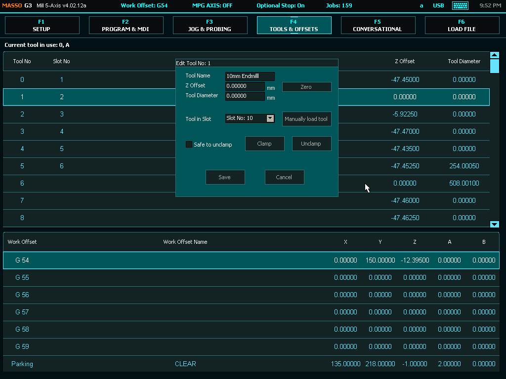
Tool Numbering
CAUTION: Please be aware that from MASSO G3 software versions 5.0 and higher, user assignable tools have changed and are now Tool 1 to 100.
INFORMATION: Depending on your software version your first user assignable tool will be either Tool 0 or Tool 1
INFORMATION: Tool Changers may be placed outside of soft Limits to protect them from accidental damage however the Auto Tool Zero must remain within soft limits.