

 Spanish
  French
  German
  Simplified Chinese
 Measure Touch probe length
For a Touch probe to be used for tool settings it needs it's length entered into the F4 tool Table.
How this is done will depend on the type of tool setter you have on your machine.
Tools setters come in 2 types
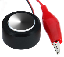
- Plate type tool setters where the touch off is simple plate of aluminum or similar. The touch is detected by completing an electrical circuit between the tool and the plate.
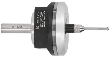
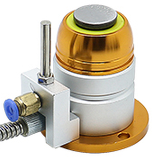
- Switch type Tool setters which have a plunger mechanism that triggers a switch.
Mounting the Touch probe
Because the Touch probe is only measured once it needs to be loaded into the spindle in a repeatable manner so that it's length does not vary.
If using an Auto Tool change this is as simple a mounting it into a tool holder.
In using manual tool change with collet nuts simple insert the Touch Probe into the Collet nut until the top of the Touch probe comes in contact with the collet nut and can go no further.
This will ensure a repeatable length each time.
Plate Tool Setter Method
CAUTION: Follow these instructions step by step or you may damage your Touch probe.
The following assumes that you are already set up with one input for Probe and another for Tool setter and that both are working correctly
Step 1
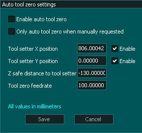
- Ensure that you have Auto tool Zero set up on your machine and works correctly.
Step 2
- Home your machine in the usual manner.
Step 3
Step 4
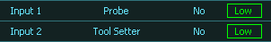
- Take note of your current tool setter and Probe input assignment
- In the F1 screen assign your Touch probe input as Tool setter
Before
After
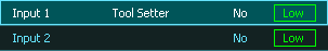
Check that the tool setter input changes to High when you touch the Touch Probe before proceeding.
Step 5
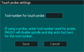
- Ensure that no tool is currently assigned as the touch probe in the F1 / Touch probe settings screen or the next step will not work.
Step 6
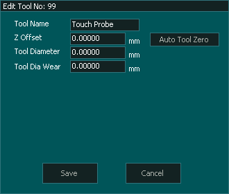
- Go to the F4 tool table and open the probe tool number by double clicking on the tool.
- Press Auto Tool Zero
- The Touch Probe will decent onto the tool setter and will stop once it touches and retract.
- The Z offset value will update to show the Touch Probe length.
- Press Save to confirm and exit
Step 7
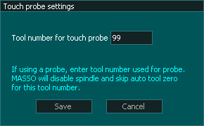
- In the F1 / Touch probe settings screen enter the Tool number of your touch probe
- Press Save to Confirm and exit
Step 8
- Reassign your Tool setter and touch probe back to their original settings.
- Ensure that the Probe input changes to High when you touch the probe
- Ensure that the Tool setter input changes to high when you touch the tool setter to ground.
- Touch Probe calibration is complete.
Switch Tool Setter Method

This style of tool setter requires a different method of calibration from the tool setter length.
Since both the Tool setter and the Touch Probe have switches built in, one will always operate before the other giving inaccurate results.
CAUTION: Follow these instructions step by step or you may damage your Touch probe.
The following assumes that you are already set up with one input for Probe and another for Tool setter.
Step 1
- Ensure that you have Auto tool Zero and Touch Probe are set up on your machine and both work correctly.
Step 2
- Home your machine in the usual manner.
Step 3
Step 4
Step 5

Step 6
Step 7
Step 8
- Go to the F4 Tool table and open the Touch Probe tool.
- Manually set the Z offset for this tool to 0 by deleting the current entry and typing in 0
- Press Save to confirm and exit
Step 9
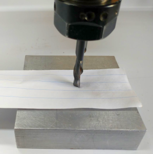
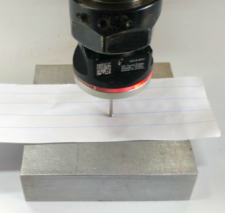
- Go to the F3 screen and jog the Touch probe down onto the reference surface.
- Leave the piece of paper on the surface as it was part of the original reference height.
- Stop when Touch probe indicates that it has touched or if you do not have an indication, use the probe indication at the top of the F2 screen.

Alternative Probing method
- An alternative method to manually jogging the probe down to the reference surface is to use a G38.2 probing cycle
- This is more accurate than jogging down as the resolution of the axis steps will be finer than the smallest jog increment.
- It will descend until the probe detects a touch and stop.
- Start with the probe close to the reference surface to minimize the probing time.
- In MDI enter the command in the following format G38.2 Z-xxx Fxxx
- Zxxx is the maximum machine coordinate you want the Z axis to move down to for probing.
- Fxxx is the probing feed rate.
- Example G38.2 Z-175 F100 (metric) or G38.2 Z-6.9 F4.0 (Imperial)
- See G38.2 for more information on using Straight probing cycles
Step 10
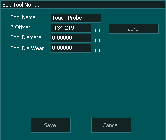
- Read the Z axis DRO and note it down.
- The -ve of this number is the Touch Probe Z offset.
- In the example below the offset is -134.219

Step 11
- Go to the F4 Tool table and open the Touch Probe tool.
- Manually set the new Z offset for this tool by deleting the current entry and typing in the new value.
- Press Save to confirm and exit
Step 12
- If you disabled Auto Tool Zero in Step 7 then enable it again.
- The Touch Probe length is now calibrated.