

 Spanish
  French
  German
  Simplified Chinese
 Best practice when wiring MASSO
The purpose of this document is to provide information on good work practices while setting up and wiring your MASSO. If you are unsure about the wiring of your machine especially mains voltage equipment, please consult a certified service technician.
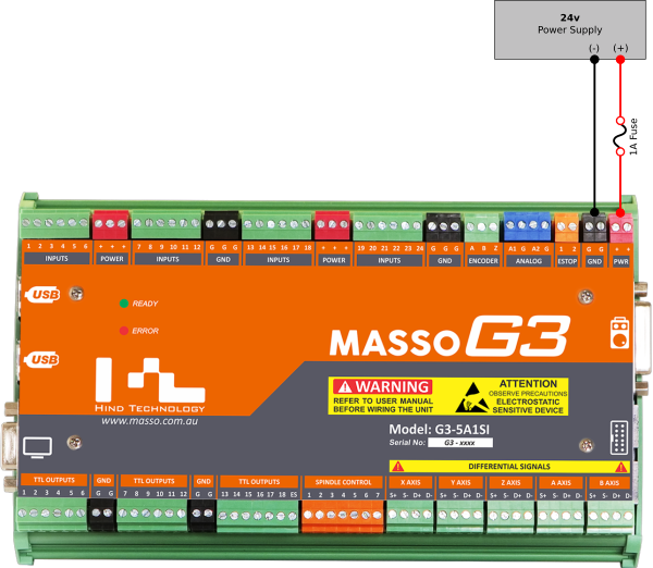
Install a Fuse
WARNING: The installation of a 1 amp fuse between your Power Supply and MASSO is required to protect against an accidental short circuit of the auxiliary power connectors on MASSO, such an event can damage the controller beyond repair.
General
- When connecting, disconnecting or making wiring changes to MASSO turn off the power at the mains. This will ensure that if you should you accidentally touch a connection point while working on your system it will not immediately damage your system.
- Check your wiring after making wiring changes to ensure you have correctly wired your system before turning back on.
- Carry out wiring in a tradesman like manner keeping the wires neat where they connect to the screw terminals as a stray wire not captured can accidentally touch the terminal next to it and cause damage. While the use of Bootlace Ferrules are not required they can help keep your wires tidy and eliminate this problem
- Use coloured wires and keep records of how you have wired your MASSO and external devices. This will assist greatly with troubleshooting should you have an issue at a later date.
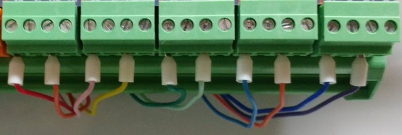
Sample colour coded wiring with Bootlace Ferrules
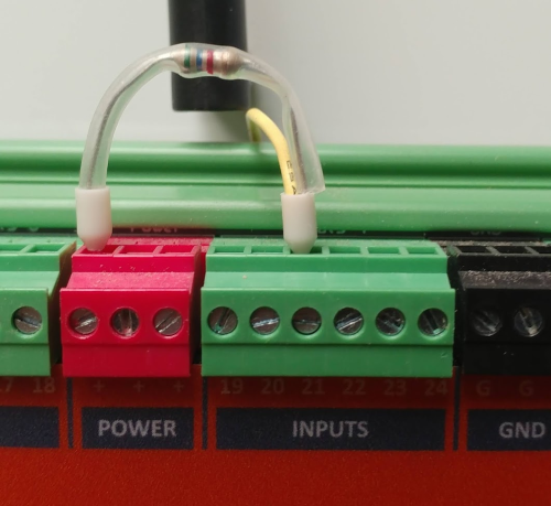
Auxiliary Power Terminals
A good use of the Red Auxiliary power terminals is to connect pullup resistors to inputs.
It is advised that the resistors should be protected from accidental contact with other circuits. Using clear heat shrink as shown below is a good way to do this.
The resistor is clearly visible but well protected.
EStop
WARNING: E-Stop wiring must be done as per your country or region's safety regulation. MASSO will put the machine in feed hold and stop spindle on E-Stop press but all drives and actuators MUST be disabled directly by E-Stop signal from the E-Stop button. MASSO's E-Stop input is only designed to alert the user that the an E-Stop has been pressed.
- An EStop output is provided on MASSO which will allow you to connect a TTL Relay module to disable your drives, spindle and other external equipment. The output is labeled ES on MASSO.
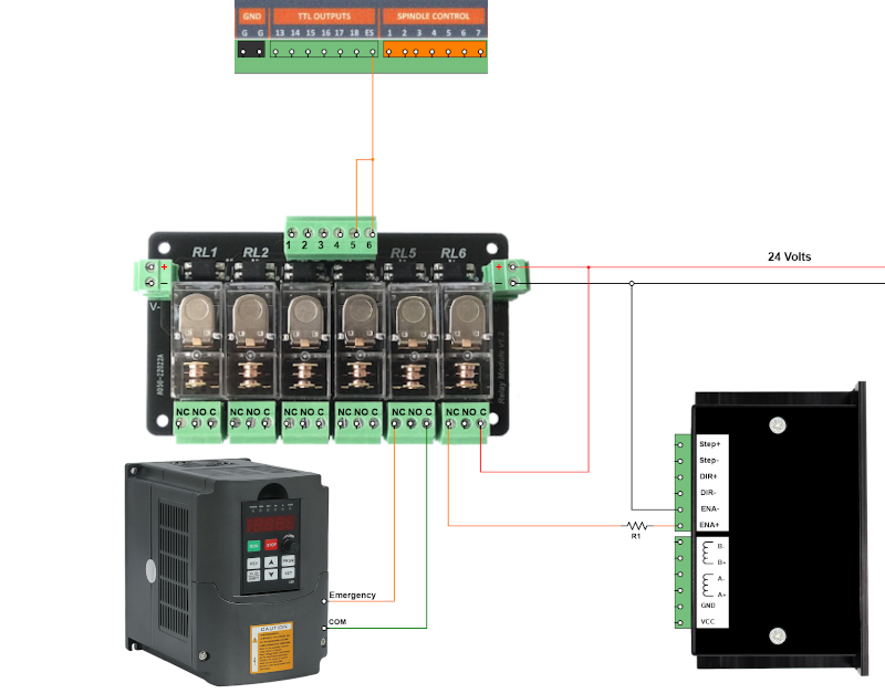
CAUTION: This diagram is for demonstration purposes only to illustrate the concept. Please consult your stepper or servo drive and VFD manuals for the correct method of connection.
INFORMATION: Up to two of the MASSO relay inputs can be connected to the ES output. If more relay contacts are required use the TTL relay output to drive a relay with multiple contacts or wire multiple MASSO TTL Relays as shown on the Estop wiring page here: EStop Wiring
INFORMATION: Note that relays will operate when the Estop is released and release when Estop is engaged.
INFORMATION: If using a MASSO G2 Relay output 7 is the EStop ouput.
VFD Wiring
WARNING: Please exercise extreme care when setting up your VFD and Spindle. These are not toys and can lead to injury or death if not handled correctly. If you have any doubt contact a suitably qualified electrical technician to assist with your installation. VFD's are complex devices that MUST be installed by a certified person and treated with respect not only because they contain High voltages but also because incorrect configuration of a VFD can destroy both the VFD and the Spindle.
- Ensure you power down your VFD before making wiring changes
Plasma Wiring
WARNING: Please exercise extreme care when setting up your plasma. These are not toys and can lead to injury or death if not handled correctly. If you have any doubt contact a suitably qualified electrical technician to assist with your installation. Plasma's are complex devices that MUST be installed by a certified person and treated with respect not only because they contain High voltages but also because incorrect connection of a plasma can cause damage to your MASSO.
- Earthing is very important to the proper operation of any plasma machine. Correct earthing not only allows the Arc to work as it should and produce good quality cuts it also reduces noise generated by the plasma from causing issues with THC and MASSO operation. Please earth your plasma in accordance with best practices and the manufacturer's instructions.
Control of External mains operated devices
WARNING: The wiring of Mains operated devices MUST be installed by a certified person in accordance with the electrical regulations of your country.
- While the MASSO relay module is rated for 240V 5amp it is recommended that you do not mix low voltage and mains voltages on the same relay module. A better option is to use the MASSO relay output to operate a separate relay or relays located elsewhere within your control cabinet. Keep all of the mains relays together and shielded against accidental contact.