

 Spanish
  French
  German
  Simplified Chinese
 Lathe Tool Calibration Steps
INFORMATION: On a lathe machine X-axis work offsets are not used or available because changing the X offset would result in a change of workpiece diameter. For setting the X offset to calibrate each tool, please follow the below procedures.
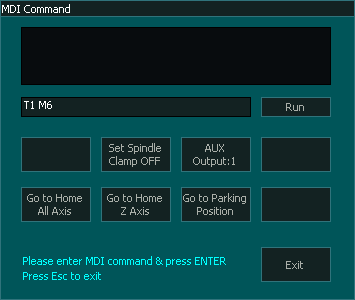
Step 1: Open the MDI window using the MDI button in F2 Screen or CTRL+M and load the tool you would like to calibrate, in this example we will be calibrating Tool No.1.
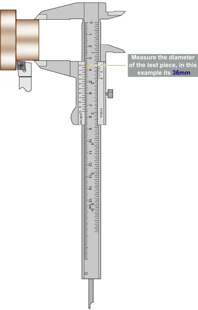
Step 2: Machine a small test piece or use an existing piece.

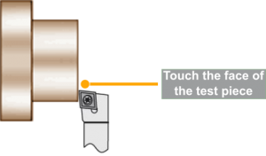
Step 3: Go to F3 – Jog/Rapid screen and touch the tool to the front face of the test piece.
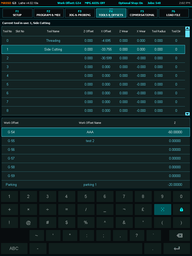
Step 4: Go to F4-Tools & Work Offset screen and open the tool number you want to calibrate.
Step 5: Give a name to the tool for your reference and click the Zero button. 
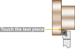
Step 6: Now go to F3 – Jog/Rapid screen and touch the tool to the side of the test piece.
Step 7: Measure the diameter of the test piece and note the value.
WARNING: Do not Jog or move the tool away unit the next step has been completed.
Step 8: Go back to F4-Tools & Work Offset screen and enter the measured diameter value in Test Piece (Dia) box and click the Touch button. 
CAUTION: Make sure to select the position of the tool depending if it is installed on the front or the backside.
Step 9: Next select if the tool is on the front side or the backside and make sure that the Z Wear and X Wear values are 0.00.
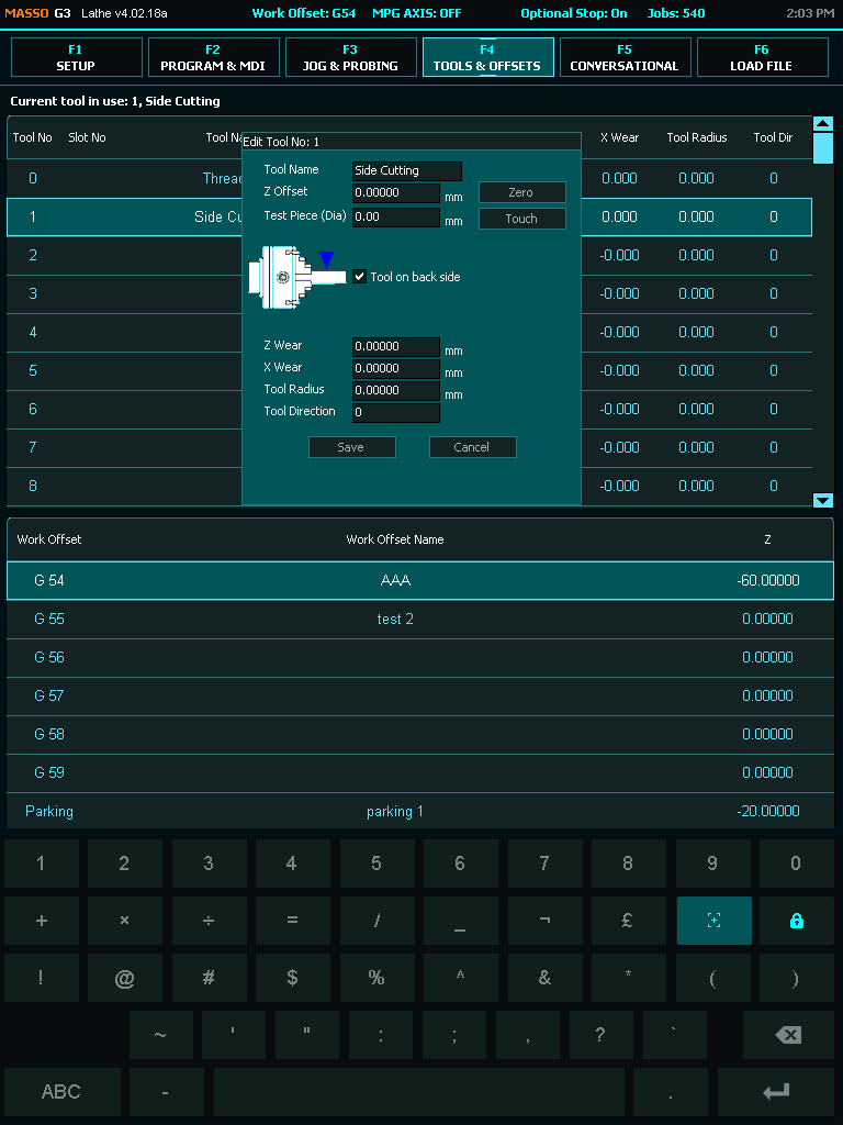
Step 10: Click the Save button to save and complete tool calibration. 