INFORMATION: This page is for the MASSO G3 and MASSO G3 Touch only.
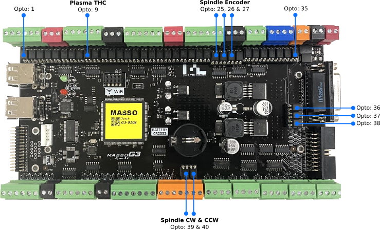
Identifying Optocouplers
- Inputs - Opto 1 to 8, 10 to 24: LTV-816 or KB817
- THC Input - Opto 9: SFH615A-2
- Spindle Encoder Inputs - Opto 25, 26 & 27: SFH615A-2
- Estop - Opto 38: LTV-816 or KB817
- MPG Inputs - Opto 28 to 37: LTV-816 or KB817
- Spindle CW & CCW Outputs - Opto 39 & 40: LTV-816 or KB817
Sourcing replacement parts
INFORMATION: Damaged Optocouplers can be purchased from one of the following suppliers, please click the link below to directly jump to the part order page:
Digi-Key: Optocoupler LTV-816
Newark Element 14: Optocoupler KB817
Mouser Electronics: Optocoupler LTV-816
Testing procedure for Inputs 1 - 24
- Remove any wire connected to the input you want to test
- Go to the F1 screen and observe the logic state of the suspected input. It will show either HIGH or LOW depending on whether the input is inverted or not.
- Test the optocoupler by connecting the +ve of the MASSO power supply through a 5.6K resistor to the input you want to test.
- On the F1 screen you should see the input change from LOW to HIGH or from HIGH to LOW.
- If the input changes from one state to the other the optocoupler is ok and does not need replacing.
- If the input does not change you can replace it using the replacement process at the bottom of this page.
- If replacing the Optocoupler does not work you can use the advanced test procedure for the Optocoupler found >>HERE<<
Testing procedure for Spindle Encoder Inputs
- Remove any wires connected to the Encoder inputs.
- Go to the F1 screen.
- Test the optocoupler by connecting the +ve of the MASSO power supply through a 5.6K resistor to the chosen encoder input.
- Encoder-A input you will see the Signal-A input of MASSO change from LOW to HIGH.
- Encoder-B input you will see the Signal-B input of MASSO change from LOW to HIGH.
- Encoder-Z input you will see the Index input of MASSO change from LOW to HIGH.
- If the input changes from one state to the other the optocoupler is ok and does not need replacing.
- If one is faulty only replace that optocoupler
Testing procedure for MPG Inputs
- Go to the F1 Screen
- Using your Pendant rotate the Manual pulse Generator, (MPG), and you will see the MPG-A and MPG-B flicker between HIGH and LOW randomly. If you see them flicker the Optocouplers are ok and do not need replacing.
- Use the Pendant Axis selector switch and rotate through Axis X, Y, Z, A & B and you will see the corresponding Axis select input change from LOW to HIGH as each is selected. If the inputs change they do not need replacing. If one is faulty only replace that optocoupler
- Use the Pendant Resolution selector switch to select between 1,10 & 100 and you will see Resolution inputs 1, 2 & 3 Change from LOW to HIGH as they are selected. If the inputs change they do not need replacing. If one is faulty only replace that optocoupler
Testing procedure for the Estop Input
- Opto No: 38 is used for the E-Stop signal.
- Remove the wire connected to Estop 2.
- Go to the F1 screen and make sure the Estop input shows LOW and is not inverted.
- Test the optocoupler by connecting the +ve of the MASSO power supply through a 5.6K resistor to the EStop2 input
- On the F1 screen, you should see the input change from LOW to HIGH.
- If the input changes from one state to the other the optocoupler is ok and does not need replacing.
Testing procedure for CW & CCW outputs
Please see the Spindle troubleshooting guide for test procedures.
Replacement Process
WARNING: Ensure that you turn the power off to MASSO and observe standard Antistatic precautions before changing an optocoupler.
CAUTION: Ensure that you observe the correct orientation of the optocoupler when replacing as they are polarity sensitive.
- Observe the polarity of the optocoupler. Take a photo if you are not sure. Each Optocoupler has a dot on it to identify pin 1
- Using a suitable pair of long nose pliers or tweezers gently remove the faulty Optocoupler from its socket. It should come out easily.
- Push the replacement Optocoupler into place until it is correctly seated. Make sure all pins are in the socket.
- Test to check that it is now working.


 Spanish
  French
  German
  Simplified Chinese