

 Spanish
  French
  German
  Simplified Chinese
 MASSO G2 Drive and Relay wiring
INFORMATION: This describes the wiring of the A & B axis on the Masso G2. For wiring of the X, Y & Z axis on the Masso G2 refer to examples in the G3 Section of this documentation.
WARNING: Axis Step and Direction signals are common Ground and precautions must be taken to wire the controller to avoid any electrical damage to the system:
- All axis outputs are common Gnd with +4 voltage signals.
- Never short-circuit the signals with each other or any other voltage.
- All signals must be isolated to other signals and connected directly to the drives
MASSO G2 A & B axis wiring examples
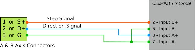
Teknic - ClearPath wiring
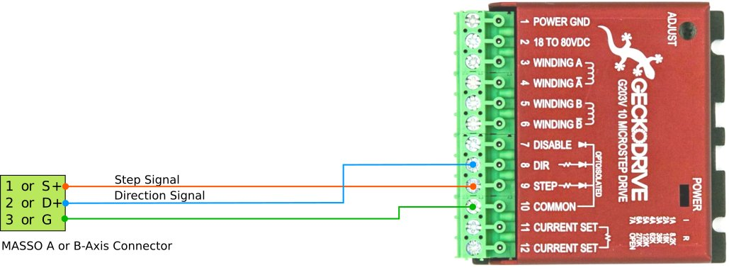
Gecko Drive 203V wiring
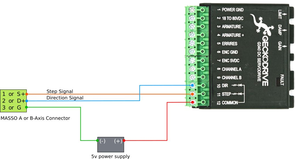
Gecko Drive G340 wiring
Gecko Drive G540 wiring
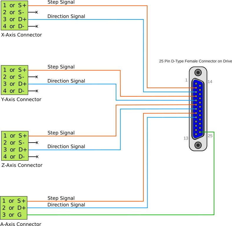
Leadshine Drive MX4660 wiring

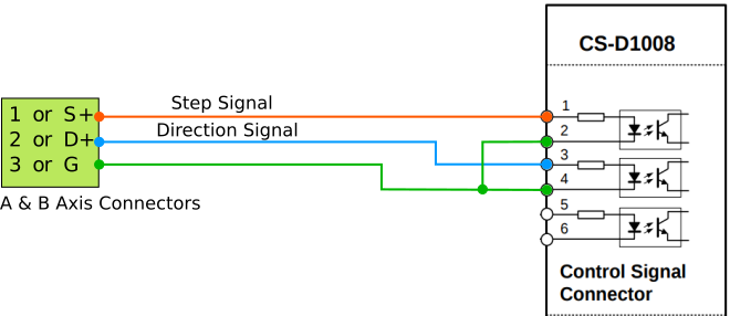
Leadshine Drive CS-D1008 wiring
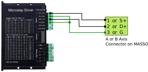
DM542A, DQ860MA wiring
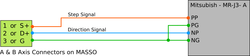
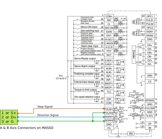
Mitsubishi - MR-J3 wiring
Panasonic - MCDHT3520 wiring
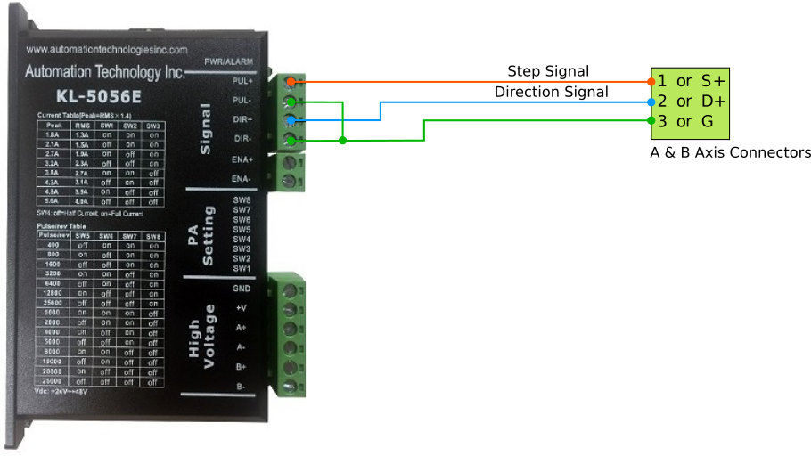
Automation Technology Inc. - KL5056E wiring
Information: If you have a MASSO-G3 or are wiring the X, Y or Z axis on A MASSO-G2 please CLICK HERE
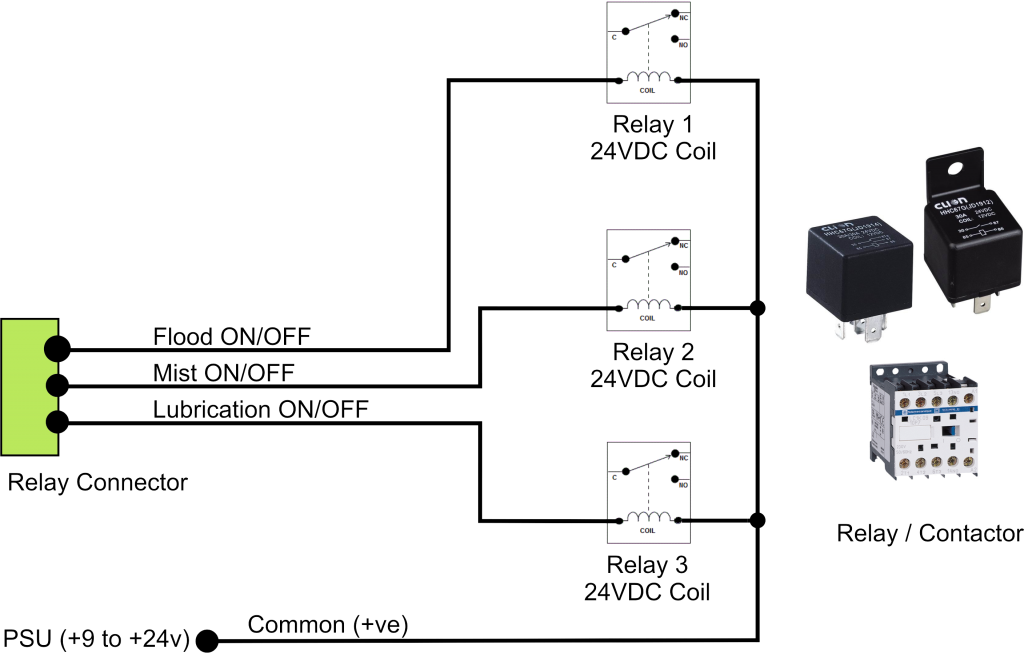
MASSO G2 Relay wiring example
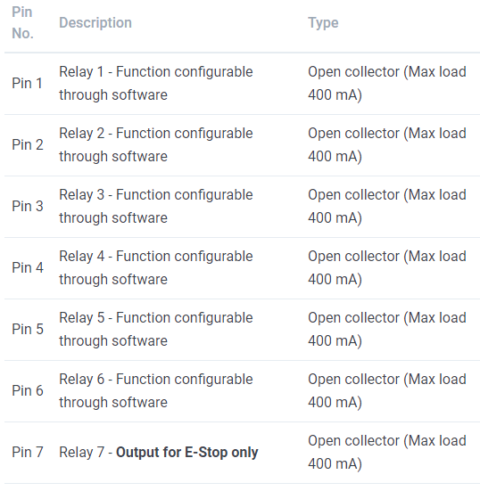
INFORMATION: Assign the desired function to the Relay output you want to use by double clicking on the output and selecting the required function from the list.
INFORMATION: All output signals can be easily inverted by selecting the input in the OUTPUTS list and pressing the space-bar key on the keyboard to invert the input signal. These settings are automatically saved.
CAUTION: The Maximum current on any relay output must not exceed 400mA or the output will be damaged.
INFORMATION: If using TTL outputs on the MASSO-G2 or you are using the Masso-G3 please follow the link below.