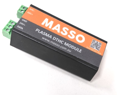
About MASSO DTHC
The MASSO DTHC (Digital Torch Height Control) module is designed to provide digital arc voltage information from a plasma source. The module is designed to be mounted at the plasma source end then connect between the MASSO G3 controller and the plasma source. The Plasma source needs to provide a divider output.
It is important to mount the DTHC next to the Plasma source rather than the controller. The DTHC is optically isolated and mounting it at the source reduces the chance of noise entering MASSO.
The digital arc voltage data is used by MASSO to monitor arc voltage levels and to adjust the torch height while cutting parts.
Having full digital information about arc voltages, the user can easily set and adjust cutting voltages for jobs using gcode commands or on screen.
This makes it very flexible and easy for the user to set all the cutting parameters of a job in a gcode file as there is no requirement to set cutting voltages manually on an external THC.
Everything is automatically loaded in when the gcode file is loaded.
INFORMATION: The DTHC module is only supported with the MASSO G3 controllers as the old G2 model does not have the required interface electronics.
Linking your DTHC to your Controller
When you purchase your MASSO DTHC it is important that you link your DTHC module to your MASSO controller.
The DTHC serial number will appear in your MY WORKSHOP portal and you will be able to choose which controller you want to link it to if you have more than one.
Once linked you can download the new software with the DTHC included and load it onto your MASSO
Linking your DTHC to your controller in MY WORKSHOP
Specifications
- Requires 24v power - The unit can be powered using the MASSO Power supply or a separate 24v power supply.
- Optically isolated interface - The unit provides optically isolated digital signals to MASSO for noise immunity and protection against high voltages from the plasma source.
- Supports multiple arc voltage ratios - The unit can be used with a plasma source with the following voltage ratios: 50:1, 30:1, 20:1 or 16:1
Arc voltage rotary switch setting
- Rotary switch position 0 - 50:1
- Rotary switch position 1 - 30:1
- Rotary switch position 2 - 20:1
- Rotary switch position 3 - 16:1
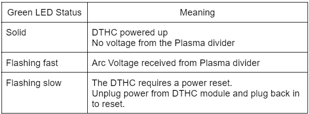
LED status indication
The MASSO DTHC module has a Green LED which can tell you the status of your DTHC module.
Wiring
CAUTION: Mount the DTHC as close to the PLASMA as practical and run cable to MASSO. Mounting the DTHC next to MASSO will cause noise related issues
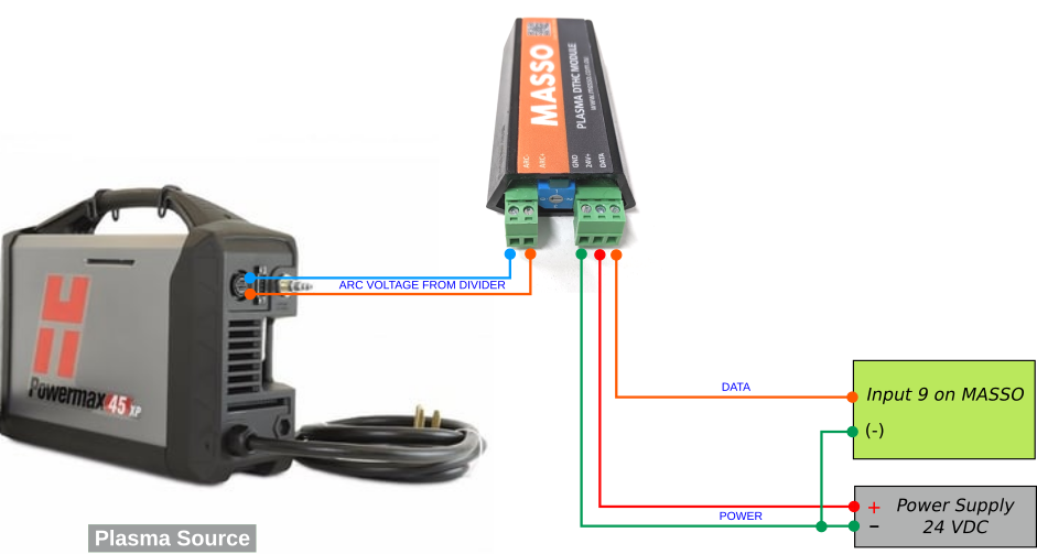
INFORMATION: You can use the MASSO power supply or a separate one. If you use a separate power supply please ensure you connect the -ve of each power supply together or the DTHC will not work.
Setting up in MASSO
INFORMATION: To use Plasma you must select tool 112 or the plasma screen will not show and the plasma features will not work. To manually change to Plasma in MDI enter the Gcode command T112 M6 and this will change you into the Plasma screen.
Configure MASSO DTHC
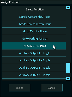
- Once the system has been wired, go to the F1-Setup screen and set Input 9, and assign it the function MASSO DTHC Input.
- Do not invert the input, ensure the invert column is set to No
- The MASSO DTHC module data signal must be wired to MASSO Input 9 and assigned the function MASSO DTHC Input, or else the DTHC module will not work.
- It is normal for Input 9 to continuously change between High & Low when the THC is connected, even when not being used. If the input is not flashing you have lost connectivity.

Enable plasma
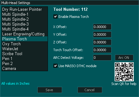
- Go to the Multi-Head Settings and select the Plasma Torch option as shown below by putting a tick in the Enable Plasma Torch box
- Enter the plasma torch offset values in reference to the spindle location. If your machine is a plasma only machine the X Y & Z offsets will be left as 0
- If the plasma head is one of several heads on your machine you will need to choose one head as the main head from which all other heads are offsets. On a combined Mill / Plasma combination machine the Main Spindle would normally be considered the main head. MASSO does not need to know which head is the main, it is up to the user to remember when configuring their machine.
- Tick the Use MASSO DTHC module option to enable MASSO DTHC logic. You will not be able to put a tick in the Use MASSO DTHC module box if you have not purchased a MASSO DTHC. When you receive your DTHC you will need to link your DTHC module to your MASSO in MY WORKSHOP then download and update your software to enable the feature.
Linking your DTHC to your controller in MY WORKSHOP
Probing inputs
- MASSO has 2 sets of probing inputs Touch and Ohmic.
- The Input logic can be inverted as required to suit your sensor. Both input logic should be LOW when not triggered and change to HIGH when triggered.
- To invert the input logic, select the required input and press the spacebar to toggle.
- You can choose which you want to use for your probing and switch between them as required by using the O parameter in the Gcode G200.or by using the on screen Ohmic button

- Note that the Ohmic selection will be overridden by G200 O parameter so if you want to use full manual selection between Ohmic and Touch then remove the O parameter from G200 and it will not override your selection.
Ohmic Sensor
- Wiring of the ohmic input will depend on the Ohmic unit used.
- There is no Torch Touch Offset when using the Ohmic sensor
- Assign an input as the Plasma Ohmic and invert as required to show logic Low when the sensor is not active.

- To invert the input logic, select the Plasma-Ohmic input and press the spacebar to toggle.
- If using you select Ohmic and the sensor does not trigger before the touch sensor you will receive an alarm. It is therefore advised that a touch sensor be installed on your system as a backup in case the Ohmic sensor fails.
Touch Sensor (Floating Head)
- The extent of Z axis travel while probing is determined by the Z axis soft limit setting.
- Ensure that your Z axis soft limits are set so that the touch sensor can reach the material surface with additional travel to operate the touch switch or a probing alarm will result.
- Assign an input as Plasma-Touch and invert as required to show logic Low when the sensor is not active.

- To invert the input logic, select the Plasma-Touch input and press the spacebar to toggle.
- In the wiring example below the Resistor is located at the MASSO end and is used to limit current in case of accidental contact with Gnd
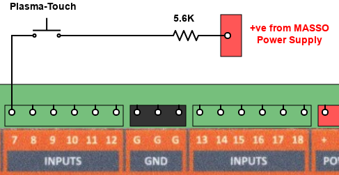
Wiring Example
- Set the Torch Touch offset in the Plasma Multi-Head Settings page to offset the height difference between the torch touching the material and the point that the switch in the torch touch detects the touch. This value is used to automatically adjust the zero point of the material.
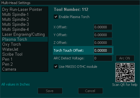
Setting the Torch Touch Offset.
- Ensure you use a thick piece of material for setting the torch offset such that is does not bend, flex or move or your measured distance will be incorrect.
- Jog the Z axis down until the torch just touches the material surface.
- Set the Z axis DRO to 0
- Jog down in single step increments until the Plasma Touch input just changes to high when using the smallest step increment setting for greater accuracy.
- Enter the Z axis DRO reading into the Torch Touch Offset box and ignore the -ve sign in the DRO reading.
- The Touch Touch offset and will always be a positive number.
Torch Breakaway
- A breakaway switch is configure a MASSO input as Plasma-Torch Breakaway.

- The input logic should be LOW when not triggered and change to HIGH when triggered.
- To invert the input logic, select the Plasma-Torch Breakaway input and press the spacebar to toggle.
- In the wiring example below the Resistor is located at the MASSO end and is used to limit current in case of accidental contact with Gnd
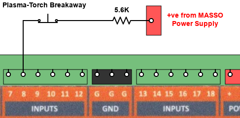
Wiring Example
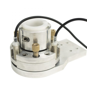
Combined Torch Touch and breakaway
- When using a torch holder that combines the touch-off and torch breakaway such as the torch holder below it requires that the breakaway is disabled while the torch is probing.
- In this setup the Plasma - Torch Breakaway input is not assigned and the Plasma - Touch input is used as both the breakaway and the touch signal.
- Simply assign Plasma - Touch to an input and if you have multiple sensors you can either just use 1 or multiplex their outputs as needed.
- The Input logic can be inverted as required to suit your sensor. The input logic should be LOW when not triggered and change to HIGH when triggered.
- To invert the input logic, select the required input and press the spacebar to toggle.
- Wiring will depend on the sensor types you have on your torch holder.

ARC Ok
MASSO Plasma has two methods of ARC detection for the user to choose from.
You can use the Arc ok output built into your Plasma unit or MASSO can derive an Arc ok by detecting the Arc voltage.
Only one method of Arc detect can be used and configuring a Plasma-Arc OK input on MASSO will disable the DTHC internal Arc detect.
Using the external Arc input is the recommended method of detection if you have one built into your Plasma.
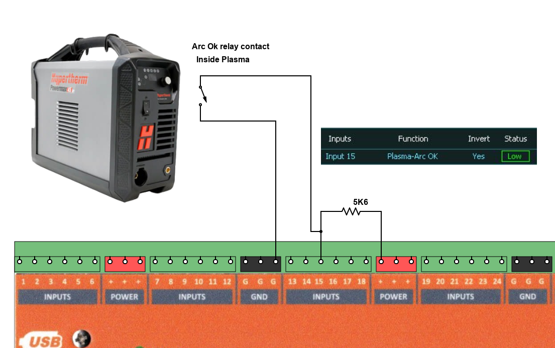
External ARC input
The user can wire up the ARC ok, ( ARC Transfer), to an external input on MASSO and this will override the built-in ARC ok in the MASSO DTHC.
This has the advantage that the Plasma machine is able to monitor the ARC status internally and provide the best feedback to MASSO as to the Arc Status.
This requires your plasma machine to have an ARC status output built n
Configure an external input on MASSO as Plasma - ARC Ok
Configuring a Plasma - ARC Ok input on MASSO Automatically disables the internal ARC Detect from the DTHC module and Calibration of the ARC Detect Voltage is not required.
Connect the ARC Ok / ARC Transfer output of your plasma to the MASSO input in accordance with your plasma manual.
Ensure that the MASSO input shows Low when the plasma is idle and changes to High when the plasma ARC is in operation.
To invert the input logic, select the Plasma-Arc OK input and press the spacebar to toggle.
If your plasma has a built in Arc Ok output, with a dry contact that is normally open when the plasma is idle, you can connect as shown below.
This method of connection will give the greatest noise immunity.
Note that the input is inverted to make the input Low when the plasma Arc is off.
MASSO DTHC ARC detect
- The MASSO can use the information from the DTHC to determine the ARC status.
- Note that if you have assigned a Plasma-Arc OK input on MASSO the MASSO DTHC Arc detect feature is disabled
- On the Multi-Head Setting page for Plasma, there is the ARC Detect Voltage which must be set up before the Arc Detect will work.
- There is an
 button that is used to calibrate the ARC Detect voltage.
Arc Detect Voltage Calibration Process
WARNING: Ensure the torch is set above the table surface where it will not burn a hole in anything, as the Plasma will start during the setup process.
This test is performed with the torch in mid air to detect the highest possible voltage from the Plasma. See the warming above.
To set the ARC Detect Voltage simply press the  Button and the Plasma arc will start.
Press the  button again, the torch will turn off and the ARC Detect Voltage box will fill in the ARC Detect voltage for you.
Press  and you will be ready to go.
- The voltage in the box will auto-fill with the voltage that MASSO will use as its Arc ok voltage.
- MASSO will also create a log Auto Detect voltage test data and save it to the Flash drive.
- This log file can be sent to MASSO for troubleshooting purposes.
- The log file is located in the MASSO\Machine Setting folder and is called Plasma_Arc_Log-001.csv
- Each time the Arc Detect rest is run a new Log file is created with an increasing number.
- Arc detect should only need to be run once.
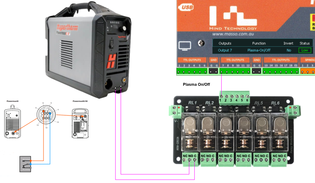
Plasma On/Off
- The Plasma On/Off output is assigned to allow MASSO to remotely turn the plasma on and off.

- The plasma can be turned on by use of the M3 command or using the Plasma button on the F2 screen

Plasma Up/Down
The Plasma up/Down is used to move the plasma torch into position when used in a Multi-head configuration. eg combined Plasma and Spindle.
This output would not normally be used on a Plasma only machine.
The Touch would be mounted on a linear rail on a Common Z axis along with all the other heads such as spindle, scribe, laser.
The chosen Multi-Head is moved into position by a pneumatic cylinder or similar when tool 112 is selected and it moves up when another tool is selected.
The output is normally Low and changes to High when selected.
To invert the output logic, select the required output and press the spacebar to toggle.
The output can be used for other purposes as decided by the user.
An example of how the Plasma Up/Down could be wired to operate a Pneumatic cylinder.

Plasma Up/Down Output
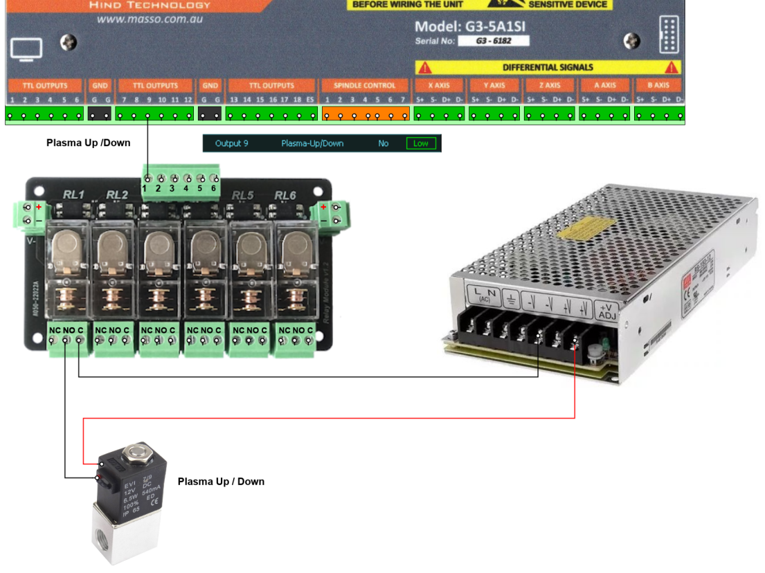
Example Plasma Up/Down Wiring
Plasma Tab
If you do not see the Plasma tab in the F2 screen please ensure that you have selected Tool 112
Ensure you have enabled Plasma in the Multi-head Plasma screen
In MDI type T112 M6 to change to the Plasma tool.
You will see 3 Tabs in the Gcode section of the screen.
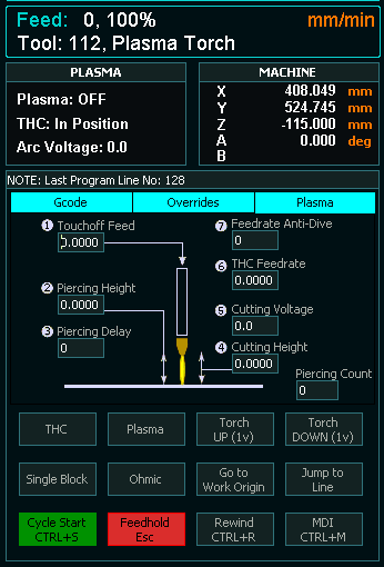
F2 Screen
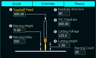
- 7 Parameters are provided on the F2 Plasma tab to allow easy adjustment of the Plasma torch while it is cutting.
- Each parameter box can be clicked on and a new value entered into the box.
- Touch off and Piercing is automated in MASSO Plasma and will occur on each M3 command before moving to the cutting height and these are controlled by parameters 1 to 4
- The THC voltage can be set directly on MASSO and changed either by entering a new value or using the Torch Up / Down buttons on screen which will change the voltage by 1 volt.
- The THC feed rate can be adjusted as needed and this adjusts the speed of the Z axis when under THC control.
- Feed rate Anti dive is a percentage of the X Y axis feed rate and should it fall below this value the Z axis will lock when under THC control to prevent the torch falling and touching the material.
- Parameters 1,2,3,4,5 & 7 can be set as part of the Gcode file. Gcode command G200
- Parameter 6 is set using Gcode command M667
- Touch off Feedrate
- Piercing Height
- Piercing Delay
- Cutting Height
- Cutting Voltage
- THC Feedrate
- Feedrate Antidive (Under development)
Overrides Tab
For easy adjustment while cutting is in progress the overrides tab has two sliders that the user can use to adjust machining speed in real time.
The Feed slider will adjust the X & Y axis feed rate speed from 10 to 100%
The THC Feed slide allows you to adjust the Z axis feed rate between 20 & 200% in real time to allow you to fine tune the Z axis movement when the THC is runing
If you find that your Z axis is hunting up and down uncontrollably seeking the correct z height under DTHC control this will allow you to slow it down until it becomes stable and follows the material correctly. Take a note of the feed rate on screen and you can use it in future Gcode files.
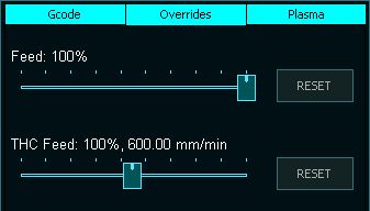
Overrides Tab
How Plasma works
- Gcode command issued eg. T112 M6. (This set MASSO to the Plasma tool.)
- The Plasma-Up/Down output goes high to move the Torch in to position. This is usually done on a multi-head machine with pneumatic cylinder and not needed is the Plasma torch is the primary head or does not need to move into position.
- When the Gcode file is loaded and run it will populate the cutting parameters into the Plasma tab using the information in the G200 Command.
- The M3 command will start the Plasma torch will automatically touch off on the material
- It will then move to the piercing height
- Start the Arc and wait for an Arc Ok
- On the receipt of an Arc ok it will wait the time specified in the Piercing Delay
- At the end of the delay it will move to the specified cutting height.
- Piercing count is incremented to allow the user to track the wear on the consumable.
- MASSO will then proceed with the Gcode file.
- If there is a MASSO DTHC installed, when the THC is turned on using M667 F??? the DTHC will assume control of the Z axis height and it will use the Cutting Voltage specified to keep a constant height above the material.
- If the X,Y Feed rate falls below the amount specified in the Anti-Dive value the Z axis will lock to prevent the Z axis crashing into the material and will resume once the feed rate returns to a valid speed. (under development)
- M666 will turn off the THC
- Parameters 1-7 can be adjusted in the Plasma Tab by selecting the box and typing in a new value. This can be done while machining is in progress to fine tune the cutting.
- Torch up and down buttons are provided on the F2 screen to allow fine tuning to the torch height. This will adjust the cutting voltage by + or - 1 volt.
- M5 will turn off the Plasma Arc.
- Changing to a different tool will cancel Plasma mode.
- The Plasma-Up/Down output goes Low to move the Torch in to the up position when a different tool is selected.
Gcode
With the introduction of the MASSO DTHC and Multi-Head a new Gcode has been introduced. G200
This Gcode is used to address parameters on the DTHC module as well as automate some of the plasma processes such as Probing, Piercing and setting cutting height.
Use of G200 is required for DTHC use.
For more information on G200 please click >>Here<<
Post Processors
Post processors have been developed to works with the new MASSO Version 5 software.
These post processors are suitable for all Plasma THC units or for Plasmas with not THC.
Please read the information provided in the G200 Gcode command to understand for it works.
Sheetcam Post processor
Fusion 360
WARNING: Please do not used the Post processor supplied with Fusion 360 as it will not work with MASSO. Please use the one from the link above.
Make your own post processor
Troubleshooting
ARC ok not working.
- If using external Plasma-ARC ok input from the Plasma ensure that the input changes from LOW to HIGH when the ARC Starts. Please see the section on External Arc Input for more information on connecting.
- If using DTHC for the ARC ok signal ensure that you do not assign a Plasma-ARC ok input assigned as this will override the DTHC arc detect preventing it from working.
- If using DTHC for the ARC ok signal you must run the Arc Detect Voltage calibration Process noted above or the Plasma will start and then stop after 5 seconds.
- If you are not connecting the ARK ok signal from your Plasma to MASSO do not assign a Plasma-ARC ok input.
THC UP / Down not working correctly
- When using the MASSO DTHC make sure that you do not have have a THC-Up or a THC-Down input configured as these will override the DTHC and prevent it from working.
- Ensure that Use MASSO DTHC module is ticked in the Multi-Head Settings / Plasma Torch Page
- THC moves too fast or too slow - check your Gcode for a feed rate in the M667 Gcode command as this defines the THC Z axis speed. eg M667 F500
- THC moves too fast or too slow - check the THC Feed rate slider on the Overrides page. Normally this is set to 100%. You can use this slider to fine tune the THC feed rate.
- THC is uncontrollable and bounces up and down - Check your THC Feed Rate as having this set too high. Slow it down by specifying a lower feed rate in your Gcode file or use the THC Feedrate slider to adjust in real time while cutting.
Probing
- Probing happens twice - You are using the wrong Gcode for the MASSO DTHC. Links to SheetCam and Fusion360 Post processors have been posted above
- Torch height too High or too low after probing - Check the Torch Height Offset in the Multi-Head Settings / Plasma Torch Page as this is used to compensate for the difference between the trigger point of the Touch switch and the Torch
- A probing alarm occurs immediately when probing starts. This indicates that the probing input is set to High and may indicate incorrect settings or a probe fault.
- A probing alarm occurs as the probe heads towards the material surface for no apparent reason. The most likely cause is that the soft limits have been reached before before the touch switch was triggered. Check your Z axis soft limits.
Alarms and messages
- Clean Material surface and press cycle start - This message is displayed when you have G200 S1 set to stop after piercing. This is used when piercing thicker material and allows the user to clean the surface before the cut continues. Setting G200 S0 will disable this feature.
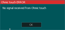
- No signal Received from Ohmic touch. - The Plasma-Torch input detected the material before the Ohmic sensor.
- Alarm Probe Error - The Z axis has reached the extent of travel before the material is detected by the touch probe.
- Alarm Torch Hit - The Z axis has detected a breakaway event. If a Plasma-Torch Breakaway input is not assigned the Plasma Touch input acts as a Breakaway signal
MASSO shows DTHC disconnected on screen.
- Check MASSO input 9 and you should see the input constantly changing between between High and low. If it is then the DTHC is working. If not please continue troubleshooting
- With the Plasma off the Green light on the DTHC should be lit solid. If the Green light is off check the DTHC power supply voltage and confirm you have 24 volts dc. If there is 24 volts present and the Green light on the DTHC is not lit up repower the DTHC and if the LED still does not light there is a problem with the DTHC unit.
- If you have a solid Green light continue with testing.
- Measure the voltage between the GND and DATA terminals of the DTHC and you should read 3 to 4 volts DC.
- If the voltage measures 10 to 13 volts between the DATA wire and GND check the DATA wire continuity between MASSO input 9 and if using a seperate power supply to power the DTHC, check that the negative of the DTHC power supply is connected to the negative of the MASSO Power supply.
- Measure the voltage between MASSO Input 9 and MASSO GND. It should be 3 to 4 volts dc and on the F1 screen the inputs should flash between High and Low. If the voltage from the DTHC is present but the input is not changing please Follow the Opto couple test process to troubleshoot the input. https://docs.masso.com.au/replacing-damaged-optocouplers-G3


 English
  Spanish
  French
  Simplified Chinese