INFORMATION: This feature is only available on MASSO G3 & MASSO Touch version 5.0 software or higher
This feature allows you to add a Laser to MASSO to use for engraving or cutting as required.
MASSO can turned the Laser on and off as well as control the power of the Laser using PWM. (Pulse Width Modulation)
This will allow the Laser to be used for Cutting, General line engraving , Dithered and Grayscale engraving.
When working with Grayscale engraving MASSO can display the image by using the Depth Map feature.
Syntax & Parameters
- T111 - Laser is defined as Tool 111 and cannot be changed. To change to Laser mode you need to load Tool 111
- M03 - Turn Laser on This turns the laser Engraving/Cutting output on with 0 intensity.
- S - This controls the Laser PWM using any number from 0 to 1000. 0 is 0% and 1000 is 100% power. The S command must be included with a G1 and is synchronized with motion.
- M05 - This turns the Laser off.
EXAMPLE Program
N10 T111 M06
N20 S0 M03
N30 G00 X0 Y0
N40 G01 X100 Y0 F600 S350
N50 G01 X100 Y100
N60 G01 X0 Y0 S0
N70 M05
Program description
- Load Laser tool 111
- Turn Laser on at 0% PWM
- Rapid Move to X0 Y0
- Move to X100 Y0 at a feed rate of 600 with Laser intensity of 35% PWM
- Move to X100 Y100 at a feed rate of 600 with Laser intensity of 35% PWM
- Move to X0 Y0 at a feed rate of 600 with Laser intensity of 0% PWM (off)
- Turn Laser off
Hardware Requirements
- Any Laser with a TTL PWM input
- Safety glasses suitable for the laser you are using.
MASSO TTL Output
- Laser on 5 volt
- Laser off 0 volt
Configuring MASSO
- Configure MASSO output 11 for the LASER Engraving/Cutting output as shown.

- No other output can be used for this function as it includes special hardware to output a PWM signal.
- An output can be assigned to move the Laser into position when Laser is selected.

- An output can be assigned for Air assist is required.

- Go to the Multi-Head setting page and select Laser Engraving/Cutting.
- Click Enable.
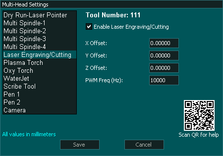
- Set the PWM Frequency for your Laser. It is recommended that you select a value of 10Khz though this will depend on the power of your Laser and the maximum feed rate you will be moving at. Since power is controlled by turning the Laser on and off very rapidly, if you have a low PWM frequency and move quickly you could get a line that has areas where the laser was on or off - - - - - - - - A frequency of 10Khz should be a good balance.
- PWM can be set between 4Khz and 60Khz
- X,Y & Z offset is the distance from the Main spindle or other Main tool if using Waterjet or Plasma. This can be measured zeroing the DRO's, making a spot with the Laser and then jog the Main spindle over to the center of the spot and reading off the X Y Y coordinates on the DRO's. These will be your offsets. The Z offset will be determined by the focus point of your Laser offset to the Z zero point of your Spindle tool. It would not be uncommon to leave the Z offset set to 0 and to manually zero the Laser when doing the job. Offsets are only needed when switching between the Laser and other tools and only if they are part of the same Gcode file.
- Configuration complete.
Displaying Laser Grayscale engravings
- For a Grayscale engraving to be able to be viewed as Grayscale, the Gcode file must include T111 M06 at the start of the file or the Depth Map view will be blank.
- To change between 2D View and Depth Map view press the button at the top right of the display area.
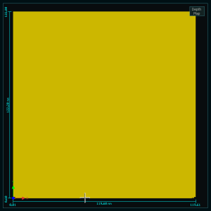
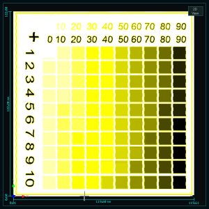
2D View and Depth Map view
- When the Laser Tool 111 is selected the display automatically changes to show Laser related information.
- This will display the Tool number 111
- Laser on / off status
- Laser Power
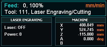
LASER Status screen
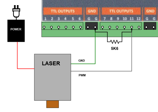
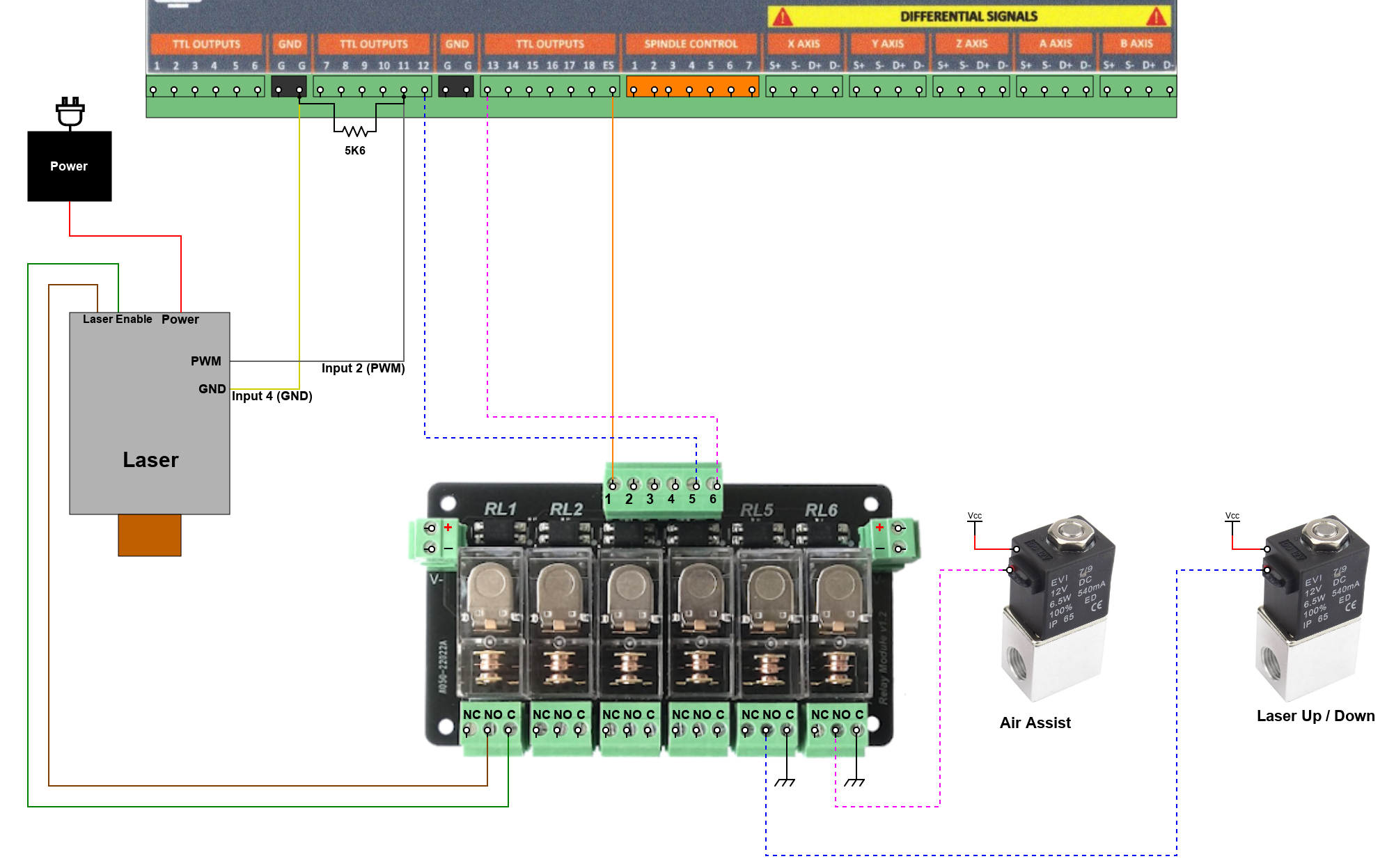
Connecting your Laser
How you connect your Laser will depend on what type of Laser you have and it's interface.
The 5.6K, 1/4W resistor installed between the PWM output and MASSO GND is important and must be installed on all Lasers that do not include a built in pull down resistor.
This is needed for correct PWM operation.
If you are unsure if your Laser has a pull down resistor built in there is no disadvantage in adding the resistor.
The connections shown below are for demonstration purposes only. please consult the user manual that came with your Laser to establish the correct connection.
MASSO uses TTL only and controls the power of the laser using PWM. (Pulse Width Modulation)
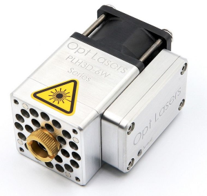
Information on how the Laser used in testing can be found here: Opt Lasers
Installing the PWM Grounding Resistor
- The 5.6K resistor 1/4W installed between the PWM output and MASSO GND is important and must be installed on all Lasers that do not include a built in pull down resistor.
- This is needed for correct PWM operation.
- If you are unsure if your Laser has a pull down resistor there is no disadvantage in adding the resistor.
- The resistor can be installed at the Laser or directly on MASSO as shown below.
- It is a good idea to insulate any resistor mounted in this manner to avoid accidental contacts. Here it has been put into clear heatshrink.
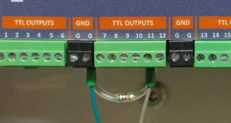
Resistor installed on MASSO
Connecting a Typical 3 Wire Laser Module
It is common for a Laser unit to have only 3 terminals Power, GND and PWM and this is a common configuration with most lasers.
The image below show several examples of typical driver boards.
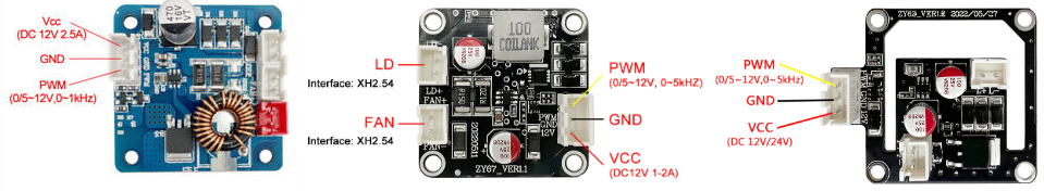
The Laser module board would commonly be found mounted on top of the Laser itself with or without a fan as shown below.
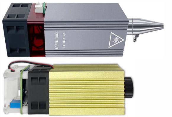
These all connect using the same method.
The 5.6K resistor 1/4W installed between the PWM output and MASSO GND is important and must be installed on all Lasers that do not include a built in pull down resistor.
This is needed for correct PWM operation.
If you are unsure if your Laser has a pull down resistor built in there is no disadvantage in adding the resistor.
Ensure that the wires carrying power from the laser power supply are correctly sized for the required current.

Connecting other outputs to your Laser
Estop
If your laser has an enable input you can connect an Estop relay to your Laser to disable it in an emergency.
If you do not have an enable as part of your Laser you could route the power supply that powers the laser through the Estop relay but be aware that when using this method that when the Estop is restored the power will be reconnected and the Laser will turn back on. This may start to burn your material is the Laser is not disabled before power is restored.
Air Assist
- An output is provided for Air assist if your laser supports it. Air assist is used to increase the cutting power of your laser as well as improve the cut quality.
- An M8 Gcode command will turn the air on and an M9 will turn it off.
- An air solenoid can be connected to turn the air on and off as required.
LASER Up/Down
- An output is provided to allow the Laser to be automatically lowered into position and raised back up once another tool is selected.
- As soon as the Laser tool is selected the Laser Up/Down output will go High. eg.T111 M6
- When another tool is selected the Laser Up/Down will go low. eg.T1 M6
- The Laser can be lowered by either a Pneumatic cylinder or a linear actuator.
- The Output can also be used to power the Laser on and off for additional safety.
WARNING: The example below is intended to illustrate the concept of how such a system could be wired. The actual wiring of your machine will depend on the hardware used and it's requirements. Please consult your user manual for the correct way to wire your selected hardware. If unsure please consult a qualified electrical engineer to assist with wiring of your machine.
Generating GCode
MASSO Laser GCode requirements are compatible with many GRBL Gcode softwares.
One of the best Laser software options is Lightburn which will allow you to engrave photos line drawings and cut parts as needed.
To see how to set up LightBurn for MASSO Laser please follow the link below.
Setting up Lightburn
Notes on Gcode format
- You must include T111 M06 at the start of the Gcode file or the Depth map view will be blank.
- The S command can be on a line of it's own before the move or it can be on the same line as the Move.
- The S command ranges 0 - 1000 so to know what percentage of total laser power you have set divide the S value by 10.
- The S command is not actioned until there is an Axis move.
Laser Safety Glasses
The most important part of any Laser is a Quality pair of safety Glasses. Unlike other CNC tools a Laser can cause serious eye damage from a distance in normal use.
Laser Safety glasses are a must and can help reduce the probability of light entering the user’s eye from a diffusely backscattered laser light.
Use quality Safety Laser glasses suitable for the Laser that you are using.
You only get one pair of eyes and they don't grow back.


 Spanish
  French
  German
  Simplified Chinese